Results 1 to 3 of 3

Thread: Material Selection for 50' Free Standing Mast with <12" Deflection

  1. #1
    Associate Engineer
    Join Date
    Feb 2015
    Posts
    1

    Material Selection for 50' Free Standing Mast with <12" Deflection

    I've been racking my brain trying to find these answers, and stumbled across this forum while reading up on the topic. I know I need modulus of elasticity, and other data points to do this math, I'm just not up on engineering principals to do it myself :(

    I live out in the country, and need to build a 50' tower on which to mount a wireless radio. I know I can do a pole with guy wires, but I would prefer to build a freestanding mast of some sort. I know the freestanding will cost more, and I am 'ok' with that.

    I've also read that this would be considered a "Class C" structure, and the guidelines for it would limit the deflection to 1/50th of the structure's height; so basically I'm looking to build a freestanding tower, at 50 feet, with no more than 12" of deflection at the top.

    The radio is basically a 20" dish, weighs only 7lbs, and has wind loading specs of 419.6 N @ 200 km/h and wind survivability rating of 200 km/h (125 mph). I live in central Texas, and found the following wind information for my zip code:
    ASCE 7-10 Wind Speeds
    (3-sec peak gust MPH*):

    Risk Category I: 105
    Risk Category II: 115
    Risk Category III-IV: 120
    MRI** 10 Year: 76
    MRI** 25 Year: 84
    MRI** 50 Year: 90
    MRI** 100 Year: 96

    ASCE 7-05: 90
    ASCE 7-93: 70

    Looking at historical wind data, back to 2010, the highest peak gusts were around 42 mph in my area. normal sustained wind speeds are around 17-18mph.

    My first thought was to build an aluminum tubular mast up against a stone outbuilding I have in the back of the property. To start it with a 3" round, 20ft pole embedded into a 3'x3'x3' hole, filled with concrete and a rebar cage, and bracket the pole at 17' against the stone outbuilding. Then use a 2.5" round 19ft pole to slide inside, overlapping 3ft, and a final bar of 2" round and 20ft long.

    I would like the radio to be serviceable, which is why I thought of this initial design. I could stand on the roof, and lower the top two sections down inside the base, and have 1ft of each extending out of the top allowing me to work on the radio.

    The below design uses 0.25" thickness pipe, but the more I research, this may not be necessary; as it seems pipe diameter is better for reducing deflection and pipe thickness is better for supporting a load. Considering the load is only 7lbs + the weight of the pipe itself, I'd appreciate your input on what thickness would be suitable.
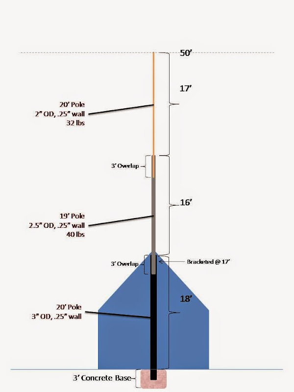


    I was thinking of using 6061 T-6 aluminum for the project.


    Another idea I had, was to use 4"x4" aluminum square tubing, and build a pivoting structure. This would be two 20ft tubes, embedded (or attached) to a 3'x3'x3' hole filled with concrete, and a center 4"x4" tube setup to pivot over.


    I'd prefer the 1st design though, based on my property.

    Any input you guys can offer would be greatly appreciated!

  2. #2
    Associate Engineer
    Join Date
    Feb 2015
    Posts
    9
    I can imagine with a 2.5" Dia 33 ft up you would have a lot of deflection under load. Factor in your joint and it could add even more deflection.

    I'm not gonna try to calculate this but why not just use a standard TV tower? You can pretty much get them free now a days and they are designed that way for a reason. Plus you could climb it.

    All I know is I wouldn't want to be anywhere near that thing. Consider the theory of levers, I couldn't help myself. With your numbers you would have 3100ft lbs of torque where the pole meets the house. That's a hell of a lot. I don't know what torque it would take to break that pole but that's pretty sketch...

  3. #3
    Associate Engineer
    Join Date
    Feb 2015
    Posts
    2
    Quote Originally Posted by Stoopalini View Post
    I've been racking my brain trying to find these answers, and stumbled across this forum while reading up on the topic. I know I need modulus of elasticity, and other data points to do this math, I'm just not up on engineering principals to do it myself :(

    I live out in the country, and need to build a 50' tower on which to mount a wireless radio. I know I can do a pole with guy wires, but I would prefer to build a freestanding mast of some sort. I know the freestanding will cost more, and I am 'ok' with that.

    I've also read that this would be considered a "Class C" structure, and the guidelines for it would limit the deflection to 1/50th of the structure's height; so basically I'm looking to build a freestanding tower, at 50 feet, with no more than 12" of deflection at the top.

    The radio is basically a 20" dish, weighs only 7lbs, and has wind loading specs of 419.6 N @ 200 km/h and wind survivability rating of 200 km/h (125 mph). I live in central Texas, and found the following wind information for my zip code:
    ASCE 7-10 Wind Speeds
    (3-sec peak gust MPH*):

    Risk Category I: 105
    Risk Category II: 115
    Risk Category III-IV: 120
    MRI** 10 Year: 76
    MRI** 25 Year: 84
    MRI** 50 Year: 90
    MRI** 100 Year: 96

    ASCE 7-05: 90
    ASCE 7-93: 70

    Looking at historical wind data, back to 2010, the highest peak gusts were around 42 mph in my area. normal sustained wind speeds are around 17-18mph.

    My first thought was to build an aluminum tubular mast up against a stone outbuilding I have in the back of the property. To start it with a 3" round, 20ft pole embedded into a 3'x3'x3' hole, filled with concrete and a rebar cage, and bracket the pole at 17' against the stone outbuilding. Then use a 2.5" round 19ft pole to slide inside, overlapping 3ft, and a final bar of 2" round and 20ft long.

    I would like the radio to be serviceable, which is why I thought of this initial design. I could stand on the roof, and lower the top two sections down inside the base, and have 1ft of each extending out of the top allowing me to work on the radio.

    The below design uses 0.25" thickness pipe, but the more I research, this may not be necessary; as it seems pipe diameter is better for reducing deflection and pipe thickness is better for supporting a load. Considering the load is only 7lbs + the weight of the pipe itself, I'd appreciate your input on what thickness would be suitable.


    I was thinking of using 6061 T-6 aluminum for the project.


    Another idea I had, was to use 4"x4" aluminum square tubing, and build a pivoting structure. This would be two 20ft tubes, embedded (or attached) to a 3'x3'x3' hole filled with concrete, and a center 4"x4" tube setup to pivot over.


    I'd prefer the 1st design though, based on my property.

    Any input you guys can offer would be greatly appreciated!
    1. Why not simply buy or at least model your design from a flag pole. Rest assured flag poles have reached 50ft, and the amount of drag from a flag that you would put on a 50ft flag pole would probably be around 7lbs.

    2. This is almost entirely a 'beam deflection' problem, and there are plenty of calculators available online to find out max deflection. Your constants would be max allowable deflection, length, and max wind force/weight of the radio, and location of application of that force. Your E and I would change with materials, but a good method to go about would be to:
    • Form a price range
    • Find materials that fit within your price range from a supplier like McMaster Carr or Granger
    • Look at the available size configurations and calculate out your I (there should be calculators for this too if you can't figure it out... Hint, I is entirely dependent on shape)
    • Plug in variations of I and E along with your max values, and calculate max deflection... When you find one that fits your specs, you have found your material and size configuation.

Posting Permissions

  • You may not post new threads
  • You may not post replies
  • You may not post attachments
  • You may not edit your posts
  •