Related Resources: calculators
AGMA Worm and Spur Gear Design Equations and Calculators
Gear Engineering and Design
Mechanics and Machine Design and Engineering
AGMA Worm and Spur Gear Design Equations and Calculators
Worm gear sets are generally rated by their capacity to handle a particular level of input power, output power, or allowable torque at a particular speed for the input or output shaft. The AGMA power rating is based on pitting and wear resistance, as this is the usual failure mode for worm sets. The AGMA rating (ANSI/AGMA 6034-B92) is based on 10 h of continuous operation under a uniform load.


Worm gear ratio:
mG = NG / Nw
where
mG = gear ratio,
NG = number of teeth in the worm gear
Nw = number of threads in the worm.
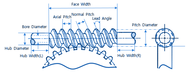
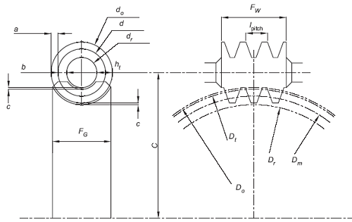
The mean worm gear diameter, dm , is within the following limits:
dm max = C0.875 / 1.07
dm min = C 0.875 / 2.0
Where:
C = center distance (Radius) (mm)
Maximum radial deflection of worm gear at pitch point is limited by:
Δwmax = 0.025 ( px )0.5
Where:
Δw = deflection of the worm gear (mm)
px = Axial pitch, (mm)
Wormgear Calculations
Preview Wormgear Calculator, torque, output power, power lost, tangential load
Torque at Wormgear:
TG = ( Wt dm ) / 2000 (N-mm)
Wt = Tangential load on wormgear in (N)
dm = Mean gear diameter (mm)
Output Torque:
Tq = ( Wt * dg) / 2000
where Tq is in (N-mm)
The input-power rating, Pinput, is given by:
Pinput = Poutput + Ploss
where Ploss is the power lost due to friction in the mesh (kW).
The output power is given by:
Poutput = ( n Wt dg ) / ( 1.91 x 10⁶ mG )
where:
n = rotational speed of the worm (rpm),
Wt = worm gear tangential force (N),
Poutput = output power (kW),
mG = gear ratio
dg = mean gear diameter (mm).
The power lost is given by:
Ploss = ( Vt Wf ) / 1000
where
Ploss = lost power (kW),
Vt = sliding velocity at the mean worm diameter (m/s)
Wf = friction force (N).
The AGMA tangential load on a worm gear is given by:
Wt = ( Cs Cm Cv dg0.8 F ) / 75.948
where
Cs = materials factor, based on manufacturing process
dg = mean diameter of the gear (mm),
F = effective face width (mm),
Cm = ratio correction factor
Cv = velocity factor.
Values for the ratio correction factor (Cm), the velocity factor (Cv), and materials factors ( Cs) can be found from tables provided in the ANSI/AGMA 6034-B92 standard ot here:
AGMA Wormgear Equations For Rating Factors
The friction force can be determined by:
Wf = ( µ Wt ) / (cosλ cosΦn )
where
µ = friction, (Based on sliding velocity)
Wt = tangential load on the worm gear tooth (N),
λ = lead angle (°),
Φn = normal pressure angle of the worm thread at the mean diameter (°)
The sliding velocity at the mean worm diameter can be determined by:
Vt = ( n dm ) / ( 19,098 cosλ )
where
n = rotational speed of the worm (rpm), and
dm = mean worm diameter (mm).
λ = lead angle (°)
The efficiency, in percent, for worm gearing is given by:
η = ( Poutout / Pinput ) x 100%
Substituting for the output power:
η = ( n Wt dm ) / ( 1.91 x 10⁷ mG Pinput ) x 100%
where
Poutout = rated output power (kW),
Pinput = rated input power (kW),
n = rotational speed of the worm (rpm),
Wt = tangential load on the worm gear (N),
dm = mean diameter of the gear (mm),
mG = gear ratio.
An outline design procedure for a worm and wheel gear set using the AGMA equations is:
1. Define the number of starts.
2. Define the center distance, C.
3. Determine a suitable worm gear diameter.
4. Determine the lead.
5. Determine the lead angle.
6. Determine the maximum recommended face width, F.
7. Determine the material factor, Cs.
8. Determine the ratio correction factor, Cm.
9. Determine the tangential velocity, Vt.
10. Determine the velocity factor, Cv.
11. Determine the tangential load, Wt.
12. Determine the coefficient of friction, f.
13. Determine the friction force, Wf.
14. Determine the output power, Poutput.
15. Determine the power lost in mesh, Ploss.
16. Determine the rated input power, Pinput.
17. Estimate the efficiency of the gear set, h.
18. Determine the output torque, Tq.
19. Establish whether the power rating and output torque are sufficient for the application.
20. If not, alter the number of starts, worm diameter, center distance, etc. to provide suitable power rating and output torque.
References and Related:
AGMA Design manual for cylindrical wormgearing. ANSI/AGMA Standard 6022-C93.
AGMA Practice for enclosed cylindrical wormgear speed reducers and gearmotors. ANSI/AGMA Standard 6034-B92.
BS 721-1:1963. Specification for worm gearing. Imperial units.
BS 721-2:1983. Specification for worm gearing. Metric units.
BS ISO TR 10828:1997. Worm gears. Geometry of worm profiles.
PD ISO/TR 14521:2010. Gears. Calculation of load capacity of wormgears.