|
|
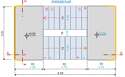
2D Static's Load Modeler and Calculator
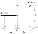
Create 2D static's model and solve for reaction
forces. |
|
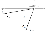
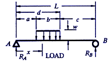
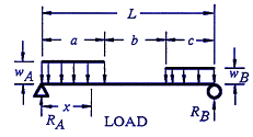
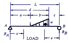
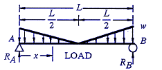
Online Simple Loads Static's 2D Modeler Calculator Simple Loads and Reactions 2D Static's Modeler Calculator |
|
|
Engineering,
Design a, Manufacturing and Related Excel SpreadSheets
Down Loads - Premium Membership Required
|
|
|
2D Finite Element Analysis Spreadsheet Calculator
Premium Membership Required |
|
|
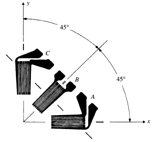
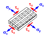
Strain Gage Rosette Equations and Calculator
applied to a specimen of a linear, isotropic
material. |
|
|
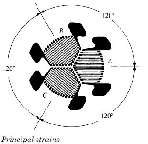
Three-Element Delta Rosette Strain Gage Equations
and Calculator applied to a specimen of
a linear, isotropic material. |
|
Finite Element Analysis Framework Python Application Script This applications is a python-based finite element analysis framework for education and research purpose |
|
|
Stress Concentration Factors |
|
|
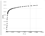
Stress-Strain Calculator and Plotted Curve Approximation
using Ramberg-Osgood Equation |
|
|
Vector Mechanics for Engineers, Static's and
Dynamics Premium membership required. Mechanics
can be defined as that science which describes
and predicts the conditions of rest or motion
of bodies under the action of forces. It is
divided into three parts: mechanics of rigid
bodies, mechanics of deformable bodies, and
mechanics of fluids. |
|
|
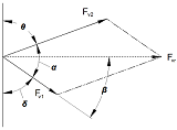
Adding Forces by the Parallelogram Resultant
of Two Forces Equation and Calculator |
|
|
Adding Forces by the Parallelogram Resultant
of Two Forces Equation and Calculator
Law of Cosines, "Cosine Rule"
for a Parallelogram(non-right angle triangle)
to calculate the resultant force vector
|
|
|
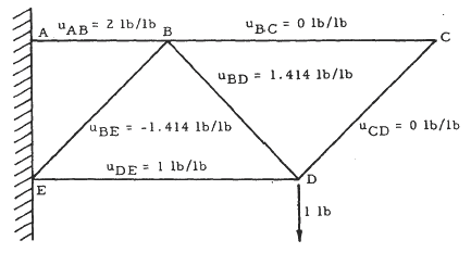
Create and analyze Structural Truss using nodes,
structural members with graphical display and
tables data results. |
|
Beams diagrams for shear, moments, angle, and deflection Python Application Script |
|
Lateral Torsional Buckling Formulae and Calculator During bending, one half of a beam is thrown into compression, and this can cause buckling
in a similar manner to the buckling of a strut. |
|
|
|
|
|
|
|
|
|
|
|
|
|
|
|
|
|
|
|
|
|
|
|
|
|
|
|
|
|
|
|
|
|
|
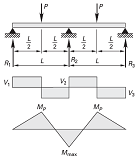
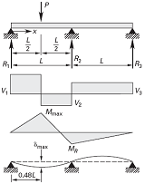
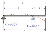
Beam Three Support Two Loads Moments, Shear and Reactions Equations and Calculator
Continuous beam of two equal spans equal concentrated loads, P, at center of each span Calculator |
|
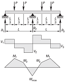
Beam Three Support Four Loads, Moments, Shear and Reactions Equations and Calculator
Continuous beam of two equal spans - four concentrated loads, P, at third points of each span Calculator |
|
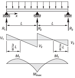
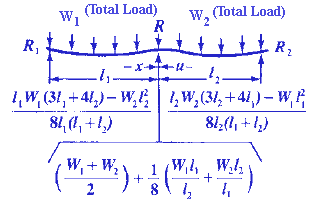
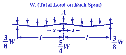
Beam Three Supports Uniform Load, Moments, Shear, Reactions and Deflections Equations and Calculator |
|
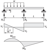
Beam Three Supports Uniform Load between two supports, Moments, Shear and Reactions Equations and Calculator |
|
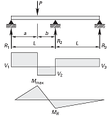
Beam Three Supports Concentrated Load between two supports, Moments, Shear and Reactions Equations and Calculator. |
|
Beam Three Supports Concentrated Load Location Defined between two supports, Moments, Shear and Reactions Equations and Calculator. |
|
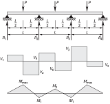
Beam Four Supports with Three Concentrated Loads Applied Supports, Moments, Shear and Reactions Equations and Calculator |
|
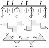
Beam Four Supports with Six Concentrated Loads Applied Supports, Moments, Shear and Reactions Equations and Calculator |
|
|
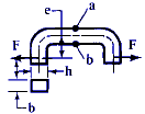
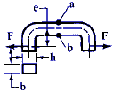
L Pipe Bend Guided Cantilever Beam Equation
and Calculator The guided cantilever beam
method of evaluating L bends can be used to
design L bends, Z bends, pipe loops, branch
take-off connections, and some more complicated
piping configurations.
|
|
|
Cantilevered Pipe Connection Spreadsheet Calculator |
|
|
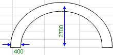
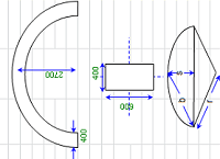
Curved Beam Stress and Deflection Design Spreadsheet
Calculator |
|
|
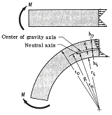
Curved Rectangular Beam Stress Formulas and
Calculator Beam stresses in curved members
do not follow the same linear variation as straight
beams, because of the variation in arc length. |
|
|
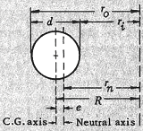
Curved Circular (Cylinder) Beam Stress Formulas
and Calculator |
|
|
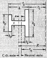
Curved I-Beam Stress Formulas and Calculator |
|
|
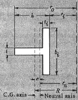
Curved T-Section Stress Formulas and Calculator
With Moment Loading Applied |
|
|
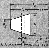
Curved Trapezoid Section Stress Formulas and
Calculator With Moment Loading Applied |
|
|
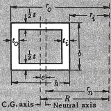
Curved Square / Rectangular Tube Section Stress
Formulas and Calculator With Moment Loading
Applied |
|
|
|
|
|
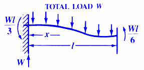
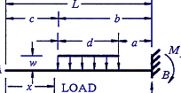
Constant
Cross Beam Section Shear, Stress and Deflections
Equations and Calculator Structural Beam
Deflection, Shear and Stress Equations and calculator
for a Beam supported One End Cantilevered with
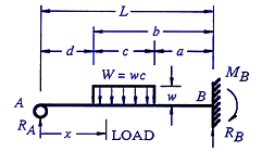
Partial Distributed Load |
|
|
|
|
|
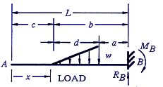
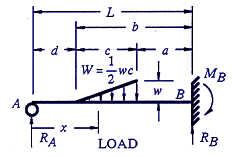
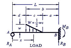
Beam
Stress, Deflection Calculator and Slope supported One End
Cantilevered with Reversed Tapered Load
Structural Beam Deflection, Shear, Slope and
Stress Equations and calculator for a Beam supported
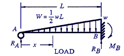
One End Cantilevered with Tapered Load. |
|
|
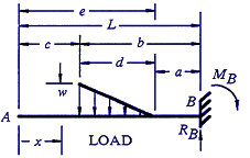
Beam Deflection Calculator,
Shear and Stress Equations and Calculator Cantilevered
with Limited Tapered Load Deflection and
Stress Beam Deflection, Shear and Stress
Equations and Calculator for a Beam supported
One End Cantilevered with Limited Tapered Load
|
|
|
Cantilevered
Beam Deflection Calculator, Shear and Stress Equations Beam Deflection, Shear and
Stress Equations and Calculator for a Beam supported
One End Cantilevered with Limited Tapered Load |
|
|
Shear,
Deflections and Stress Calculator Equations
for a Beam Triangular Distributed Load Beam
Deflection, Shear and Stress Equations and Calculator
for a Beam supported One End, Pin Opposite End
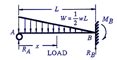
and Triangular Distributed Load |
|
|
|
|
|
|
|
|
|
|
|
Beam
Stress and Deflection Calculator
with Fixed Ends Tapering Loading |
|
|
|
|
|
|
|
Calculator
for a Beam supported One End, Pin Opposite End
and Single Moment at End Applied Deflection
and Stress Calc Beam Deflection, Shear and
Stress Equations and Calculator for a Beam supported
One End, Pin Opposite End and Single Moment
at End Applied
|
|
|
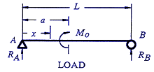
Beam
Deflection Calculator supported One End, Pin Opposite End and Single
Moment at Defined Center Location Shear and Stress Equations
and Calculator for a Beam supported One End,
Pin Opposite End and Single Moment at Defined
Center Location |
|
|
Beam Stress
Equations and Calculator for a Beam supported
One End, Cantilevered
Single Load at End Deflection and Stress
Equations and Calculator for a Beam supported
One End, Cantilevered at Defined Location and
Single Load at End |
|
|
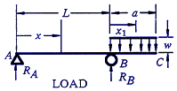
Beam Stress
Equations and Calculator supported
One End, , Cantilevered at Defined Location
and Distributed Load Between Supports Shear,
Deflection and Stress Equations and Calculator
for a Beam supported One End, Cantilevered at
Defined Location and Distributed Load Between
Supports |
|
|
Stress
Equations and Deflection Calculator for a Beam
supported One End, Cantilevered at Defined Location
and Single Load Between Supports Shear,
Deflection and Stress Equations and Calculator
for a Beam supported One End, Cantilevered at
Defined Location and Single Load Between Supports |
|
|
Stress &
Deflection Equations and Calculator for a Beam
Supported One End, Cantilevered at Defined Location
and Single Moment Applied at End Stress
Equations and Calculator for a Beam Supported
One End, Cantilevered at Defined Location and
Single Moment Applied at End |
|
|
Stress &
Deflection Equations and Calculator for a Beam
Supported One End, Cantilevered at Defined Location
and Uniform loading Applied Stress Equations
and Calculator for a Beam Supported One End,
Cantilevered at Defined Location and Uniform
loading Applied |
|
|
Stress &
Deflection Deflection Calculator Equations
Beam Supported Uniform loading Applied on Cantilevered
End Stress Deflection Equations and Calculator
Beam Supported Uniform loading Applied on Cantilevered
End |
|
|
Stress &
Deflection Equations and Calculator Beam Supported
Uniform loading Applied Stress Deflection
Equations and Calculator Beam Supported Uniform
loading Applied |
|
|
Stress
Deflection Calculator and Moment Equations
Beam Supported Uniform loading Applied Stress
Deflection Moment Equations and Calculator Beam
Supported Uniform loading Applied |
|
|
|
|
|
|
|
|
Beam
Stress & Deflection Calculator
Free and Guided on One End Structural Beam
Stress and Beam Deflection calculator
for a Beam with moment force applied |
|
|
Beam
Stress & Deflection Calculator
Moment Applied at Defined Location Beam
Stress & Deflection Equations / Calculator
Moment Applied at Defined Location |
|
|
Stress
Deflection Moment Calculator Beam
Supported Partial Uniform loading Applied
Stress Deflection Moment Equations and Calculator
Beam Supported Partial Uniform loading Applied |
|
|
Stress
Deflection Moment Calculator Beam
Supported Partial Distributed Uniform loading
Applied Stress Deflection Moment Equations
and Calculator Beam Supported Partial Distributed
Uniform loading Applied |
|
|
Stress
Deflection Moment Calculator Beam
Supported Tapering Load Applied Stress Deflection
Moment Equations and Calculator Beam Supported
Tapering Load Applied |
|
|
Stress
Deflection Strain Calculator Beam
Supported Tapering Load Applied Stress Deflection
Strain Equations and Calculator Beam Supported
Tapering Load Applied |
|
|
Stress
Deflection Moment Calculator Beam
Supported Partial Tapering Load Applied
Stress Deflection Moment Equations and Calculator
Beam Supported Partial Tapering Load Applied |
|
|
Stress
Deflection Strain Moment Calculator
Beam Supported Partial Tapering Load Applied
Stress Strain Deflection Moment Equations and
Calculator Beam Supported Partial Tapering Load
Applied |
|
|
|
|
|
|
|
|
|
|
|
|
|
|
|
|
|
|
|
|
Beam
Stress Deflection Calculator with
Partial Uniform Loading
Beam Stress Equations and Beam Deflection calculator for
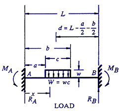
a Beam Fixed at Both Ends with Partial Uniform
Loading. |
|
|
Beam
Stress Deflection Calculator with
Partial Tapering Loading Beam Deflection Calculator
and Stress Equations for
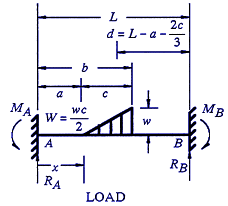
a Beam Fixed at Both Ends with Partial Tapering
Loading. |
|
|
Beam
Stress Deflection Calculator with
Fixed Ends Tapering Loading Beam Stress
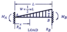
Deflection Equations / Calculator with Fixed
Ends Tapering Loading |
|
|
Beam
Stress Deflection Calculator with
Fixed Ends Moment Applied Beam Stress Deflection
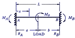
Equations / Calculator with Fixed Ends Moment
Applied |
|
|
|
|
|
|
|
|
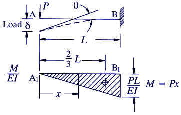
Area Moment Methods to Calculate Deflection
in Beams No Calculator! Calculation of deflections
and redundant reactions for beams on two supports
can be made by the use of the area-moment method. |
|
|
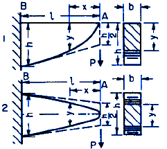
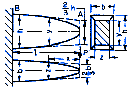
Beam
Parabolic Deflection Equation Calculator with
Variable Shape Fixed End Single Concentrated
Force Applied |
|
|
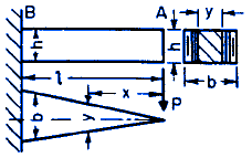
Beam
Stress Deflection Equations Calculator Triangular
Shape Fixed End Single Concentrated Force
Applied |
|
|
Beam
Cubic Parabola Shape Deflection Equation Calculator
with Variable Shape Fixed End Single Concentrated
Force Applied |
|
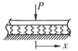
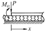
Beam on Elastic Foundation Calculator and Equations Loading Case 1 |
|
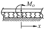
Beam on Elastic Foundation Calculator and Equations Loading Case 2 - Beam with moment loading at center |
|
|
|
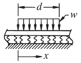
Beam with Distributed Loading on Elastic Foundation Calculator and Equations Loading Case 4 |
|
|
Flexural Strengthening of Reinforced Concrete
Beam with FRP Laminates Spreadsheet Calculator |
|
|
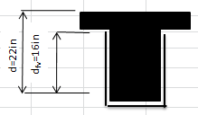
Shear Strengthening of T-beam with FRP Spreadsheet
Calculator |
|
|
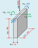
RC Shear Wall Analysis and Design Spreadsheet
Calculator |
|
|
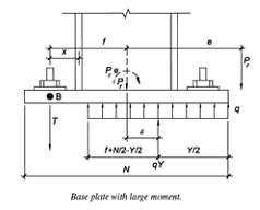
Base plate with Large Moment to AISC LRFD
Spreadsheet Calculator |
|
|
Combined Stress Circular Cantilever Beam in
Direct Compression and Stress Equations
and Deflection Calculator Circular Cantilever Beam
in Direct Compression. For every calculated
normal stress there is a corresponding induced
shear stress; the value of the shear stress
is equal to half that of the normal stress. |
|
|
|
|
|
Beam in Direct Compression and Stress
Equations and Calculator Circular Cantilever
Beam in Direct Compression Equations
and Deflection Calculator |
|
|
|
|
Design of a Power Transmission Shaft under Fatigue Loading Using ASME Code. Based on American Society of Mechanical Engineers (ASME) Standard B106.1M:1985 |
|
|
Combined Loading on Circular Beam or Shaft in
Direct Compression Stress Equation
and Deflection Calculator Combined Loading on Circular
Beam or Shaft in Direct Compression and Beam Deflection Calculator |
|
|
|
|
|
|
|
|
|
|
|
|
|
|
|
|
|
|
|
|
|
|
|
|
|
|
|
|
|
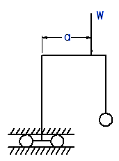
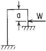
Concentrated Load on the Horizontal Member Elastic
Frame Equations and Calculator |
|
|
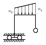
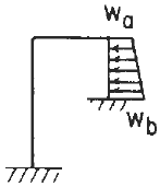
Distributed Load on the Horizontal Member Elastic
Frame Deflections Equations and Calculator |
|
|
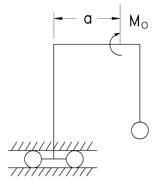
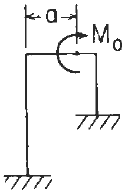
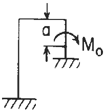
Frame Deflections with Concentrated Moment Applied
on Horizontal Member Equations and Calculator |
|
|
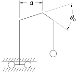
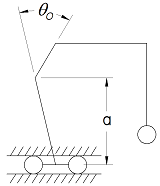
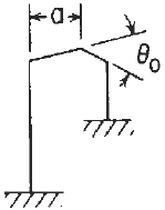
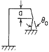
Frame Deflections with Concentrated Angular
Displacement Applied on Horizontal Member Calculator |
|
|
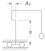
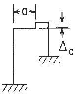
Frame Deflections with Concentrated Lateral
Displacement Applied on Horizontal Member Equations
and Calculator |
|
|
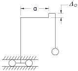
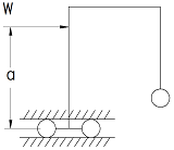
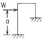
Frame Deflections with Concentrated Load Applied
to Vertical Member Equations and Calculator |
|
|
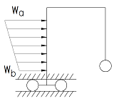
Frame Deflections with Distributed Load Applied
to Left Vertical Member Equations and Calculator |
|
|
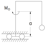
Frame Deflections with Concentrated Moment Applied
to Left Vertical Member Equations and Calculator |
|
|
Frame Deflections with Concentrated Angular
Displacement Applied to Left Vertical Member
Equations and Calculator |
|
|
Frame Deflections with Concentrated Lateral
Displacement Applied to Left Vertical Member
Equations and Calculator |
|
|
Frame Deflections with Concentrated Load Applied
to Right Vertical Member Equations and Calculator |
|
|
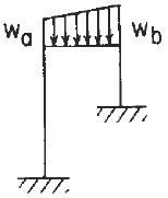
Frame Deflections with Distributed Load Applied
to Right Vertical Member Equations and Calculator |
|
|
Frame Deflections with Concentrated Moment Applied
to Right Vertical Member Equations and Calculator |
|
|
Frame Deflections with Concentrated Angular
Displacement Applied Right Vertical Member Equations
and Calculator |
|
|
Frame Deflections with Concentrated Lateral
Displacement Applied Right Vertical Member Equations
and Calculator |
|
|
Frame Deflections with Uniform Temperature Rise
Equations and Calculator |
|
|
Frame Deflections with Uniform Temperature Differential
Between Outside and Inside Equations and Calculator |
|
|
Frame Deflections with Concentrated Load on
the Horizontal Member Equations and Calculator.
Left vertical member guided horizontally, right
end pinned. |
|
|
Distributed Load Elastic Frame Deflection Left
Vertical Member Guided Horizontally, Right
End Pinned Equation and Calculator. |
|
|
Concentrated Moment on the Horizontal Member
Elastic Frame Deflection Left Vertical Member
Guided Horizontally, Right End Pinned Equation
and Calculator. |
|
|
Concentrated Angular Displacement on the Horizontal
Member Elastic Frame Deflection Left Vertical
Member Guided Horizontally, Right End Pinned
Equation and Calculator. |
|
|
Concentrated Lateral Displacement on the Horizontal
Member Elastic Frame Deflection Left Vertical
Member Guided Horizontally, Right End Pinned
Equation and Calculator. |
|
|
Concentrated load on the Left Vertical Member
Elastic Frame Deflection Left Vertical Member
Guided Horizontally, Right End Pinned Equation
and Calculator. |
|
|
Distributed Load on the Left Vertical Member
Elastic Frame Deflection Left Vertical Member
Guided Horizontally, Right End Pinned Equation
and Calculator |
|
|
Concentrated Moment on the Left Vertical Member
Elastic Frame Deflection Left Vertical Member
Guided Horizontally, Right End Pinned Equation
and Calculator |
|
|
Concentrated Angular Displacement on Left Vertical
Member Elastic Frame Deflection Left Vertical
Member Guided Horizontally, Right End Pinned
Equation and Calculator |
|
|
Concentrated Lateral Displacement on Left Vertical
Member Elastic Frame Deflection Left Vertical
Member Guided Horizontally, Right End Pinned
Equation and Calculator. |
|
|
Concentrated Load on Right Vertical Member Elastic
Frame Deflection Left Vertical Member Guided
Horizontally, Right End Pinned Equation
and Calculator.
|
|
|
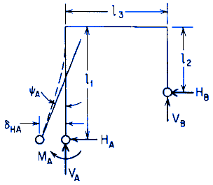
Reaction and deflection formulas for in-plane
loading of elastic frame with mounting ends
fixed formulas and calculator. Roark's Formulas
for Stress and Strain, Seventh Edition, Table
8.2 reference loading number 5a. |
|
|
|
|
|
|
|
|
|
|
|
|
|
|
|
|
|
|
|
|
|
|
|
|
|
|
|
|
|
|
|
|
Reaction and deflection formulas for in-plane
loading of elastic frame with mounting ends
fixed and distributed load on the right vertical
member formulas and calculator. Roark's
Formulas for Stress and Strain, Seventh Edition,
Table 8.2 reference loading number 5L. |
|
|
|
|
|
|
|
|
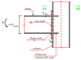
Structural Shapes Moment Connections Design
Spreadsheet Calculator |
|
|
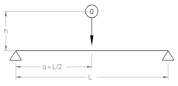
Stress from Drop Load of Beam Supported on Both
Ends and Struck in the Center. |
|
|
|
|
|
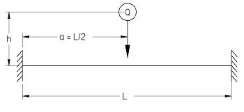
Stress from Drop Load of Beam Fixed on Both
Ends and Struck at Center Equations and
Calculator. |
|
|
Curved Beam Design Spreadsheet Calculator
Excel spreadsheet analysis - premium membership
required |
|
|
Capacity of Standard Universal Beams According
to BS5950 Spreadsheet Calculator - premium
membership required |
|
|
Aircraft Airframe Structural Design Premium
Membership Required to view Document/Book |
|
|
Design and Analysis of Leaf Springs using FEA
Approach This is a general study the design
and analysis of leaf spring. |
|
|
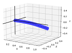
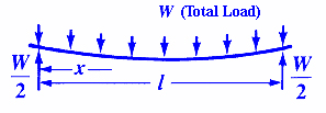
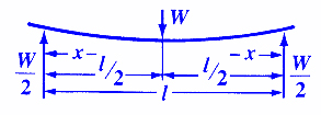
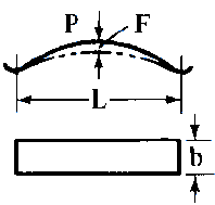
Flat spring supported on both ends design equations
and calculator |
|
|
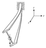
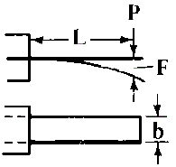
Flat spring cantilevered design equations and
calculator |
|
|
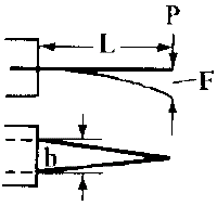
Flat spring cantilevered design triangular geometry
equations and calculator |
|
|
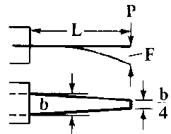
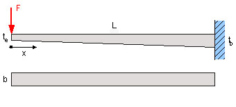
Tapered Flat spring cantilevered design equations
and calculator |
|
|
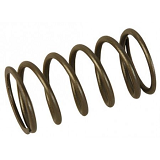
Stresses in Helical Springs Produced by Shocks
Formulas and Calculator |
|
|
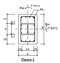
Circular Composite Beams and Columns Design
Spreadsheet Calculator |
|
|
Composite Rectangular Beam and Columns Spreadsheet
Calculator |
|
|
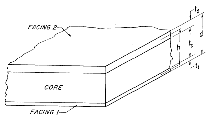
Cored Laminate Composite Stiffness Calculator
Here also are discussed the effects of facing
and core stiffness on sandwich stiffness
so that the degree of approximation implied
by simplified formulas neglecting facing
and core stiffness is known.
|
|
|
|
|
|
|
|
|
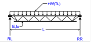
K-Series Joist Deflection and Stress Analysis
Calculator K-Series Joists Specifications
Designations: 8K1 to 30K12 Depths: 8 to
30 in. Standard Seat Depth (Height): 2.5
in. Span Range: 8 to 60 ft. ASD Load Range:
127 to 550 plf LRFD Load Range: 190 to 825
plf Maximum Span/Depth Ratio: 24
|
|
|
|
|
|
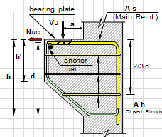
Monolithic Corbels and Brackets According To
ACI 318 - 99 Spreadsheet Calculator |
|
|
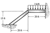
Staircase Analysis and Design Spreadsheet Calculator |
|
|
Slab Canopy Design Spreadsheet Calculator |
|
|
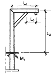
Lifting Boom, Davits Application and Design
Equations
Davits refer to single mechanical
arms with a winch for lowering and raising objects.
A davit is commonly used system designed to
lower an emergency lifeboat from a ship to the
embarkation level to be boarded.
|
|
|
Tension Compression Machine Feature Equation
and Calculator |
|
|
|
|
|
|
|
|
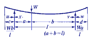
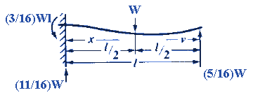
Single-Span Beam Deflection for Simple, Propped,
Fixed or Cantilever Beams. - Include Shear and
Moment Diagram.
NOTE: Large web
page that opens in pop-up window.
|
|
|
|
|
|
|
|
|
|
|
|
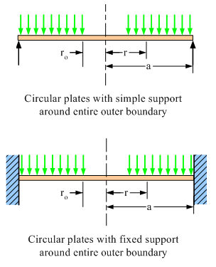
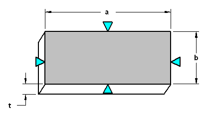
Flat Plate Deflection & Stress Calculator
Assumptions: The plate is flat, of uniform
thickness, and of homogeneous isotropic
material; the thickness is not more than
about one quarter of the least transverse
dimension, and the maximum deflection is
not more than about one-half the thickness;
|
|
|
|
|
|
|
|
|
Honeycomb Beam & Panel Calculations Spreadsheet
Calculator |
|
|
|
|
|
|
|
|
|
|
|
|
|
|
|
|
|
|
|
|
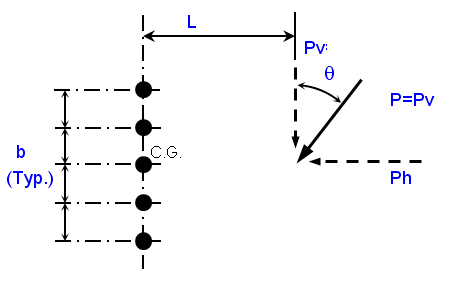
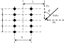
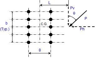
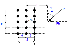
Eccentric Loads on Bolt Groups for Two Vertical
Rows of Bolts Fixed Separation of 8"
Based on the Instantaneous Center of Rotation
Method and Alternate Method 2 Using Table XII
from AISC 9th Ed. Manual (ASD) - page 4-63 .
Vertical Row Bolt Spacing at 8 " |
|
|
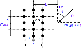
Eccentric Loads on Bolt Groups for Two Vertical
Rows of Bolts Bolt group instantaneous center
analysis for three vertical rows spaced at 3 "
spacing |
|
|
Eccentric Loads on Bolt Groups for Two Vertical
Rows of Bolts Bolt group instantaneous center
analysis for three vertical rows spaced at 6"
spacing |
|
|
Structural Eccentric Loading on Bolt Group -
For Two Vertical Rows Calculator Fixed Vertical
Separation of 5-1/2 " Based on the Instantaneous
Center of Rotation Method and Alternate Method
2 Using Table XII from AISC 9th Ed. Manual (ASD)
- page 4-63
|
|
|
|
|
|
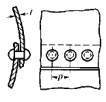
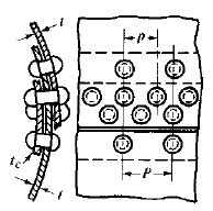
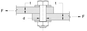
Single-Riveted Lap-Joint Formulas for Stress
and Strength Design Equations and Calculator |
|
|
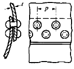
Double-Riveted Lap-Joint Formulas and Calculator
for Stress and Strength Design
|
|
|
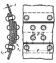
Single-Riveted Lap-Joint with Inside Cover Plate
Formulas and Calculator for Stress and Strength
Design |
|
|
Double-Riveted Lap-Joint with Inside Cover Plate
Formulas and Calculator for Stress and Strength
Design. |
|
|
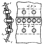
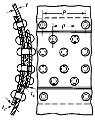
Double-Riveted Butt Joint Plate Formulas and
Calculator for Stress and Strength Design |
|
|
Triple-Riveted Butt Joint Plate Formulas and
Calculator for Stress and Strength Design |
|
|
Collar Bolt Flange Pressure Vessel Spreadsheet
Calculator |
|
Wood Column Stability Factor Formulas and Calculator |
|
|
Ideal Pinned Column Buckling Calculator
When a column buckles, it maintains its
deflected shape after the application of
the critical load. In most applications,
the critical load is usually regarded as
the maximum load sustainable by the column.
|
|
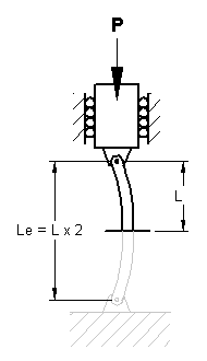
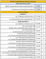
Wood Structural Design Effective Length for Bending Members Formula and Calculator |
|
|
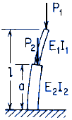
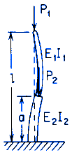
Column Loading and Elastic Stability Formulae
and Calculator Stepped straight bar under
end load P and intermediate load P2;
upper end free, lower end fixed.
|
|
|
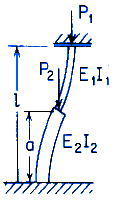
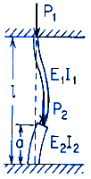
Column Loading and Elastic Stability Formulae
and Calculator Case 1b Stepped straight
bar under end load P1 and intermediate
load P2; both ends pinned |
|
|
|
|
|
|
|
|
|
|
|
|
|
|
|
|
|
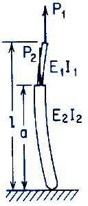
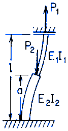
Column Loading and Elastic Stability Formulae
and Calculator Case 2c Stepped straight
bar under tensile end load P1 and intermediate
load P2; upper end guided, lower end fixed. |
|
|
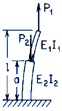
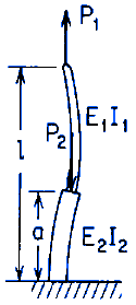
Column Loading and Elastic Stability Formulae
and Calculator Case 2d Stepped straight
bar under tensile end load P1 and intermediate
load P2; upper end pinned, lower end fixed. |
|
|
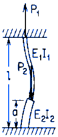
Column Loading and Elastic Stability Formulae
and Calculator Case 2e. Stepped straight
bar under tensile end load P1 and intermediate
load P2; both ends fixed |
|
|
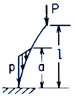
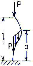
Column Loading and Elastic Stability Formulae
and Calculator Case 3a1 Uniform straight
bar under end load P and a uniformly distributed
load p over a lower portion of the length; several
end conditions. Upper end free, lower end fixed. |
|
|
|
|
|
|
|
|
|
|
|
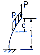
Column Loading and Elastic Stability Formulae
and Calculator Case 3B1. Uniform straight
bar under end load P and a uniformly distributed
load p over an upper portion of the length;
several end conditions Upper end free, lower
end fixed. |
|
|
|
|
|
|
|
|
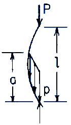
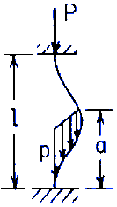
Column Loading and Elastic Stability Formulae
and Calculator Case 3B4. Uniform straight
bar under end load P and a uniformly distributed
load p over an upper portion of the length;
both ends fixed. |
|
|
|
|
|
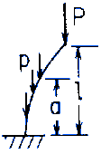
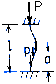
Column Loading and Elastic Stability Formulae
and Calculator Case 3C2. Stepped straight
bar under end load P and a distributed load
of maximum value p at the bottom linearly decreasing
to zero at a distance a from the bottom Both
ends pinned. |
|
|
|
|
|
|
|
|
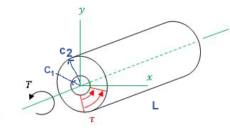
Shaft Torsional Deflection and Rigidity Formulas
and Calculator Shaft Torsional Deflection
Rigidity is based on the permissible angle of
twist. The amount of twist permissible depends
on the particular application, and varies about
0.8 deg. per foot for machine shafts to about
1.0 deg per foot for line shafting. |
|
Rod of Nonuniform Diameter, Change of Length Under Axial Force Formula and Calculator |
|
|
|
|
|
Torsional Deformation and Stress Solid Circular
Section Equations and Calculator |
|
|
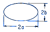
Torsional Deformation and Stress Solid Elliptical
Section Equations and Calculator |
|
|
Solid Square Section Torsional Deformation and
Stress Calculator and Equations |
|
|
Torsional Deformation and Stress Solid Rectangular
Section Equations and Calculator |
|
|
Torsion Deformation and Stress Hollow Rectangle
Thin Wall Tube Section Equations and Calculator
|
|
|
Torsional Deformation and Stress Solid Triangular
Section Equations and Calculator |
|
|
Torsional Deformation and Stress Solid Isosceles
Triangle Section Equations and Calculator |
|
|
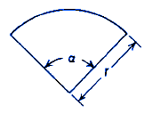
Torsional Deformation and Stress Solid Circular
Segmental Section Equations and Calculator |
|
|
Torsional Deformation and Stress Circular Segmental
Section Equations and Calculator |
|
|
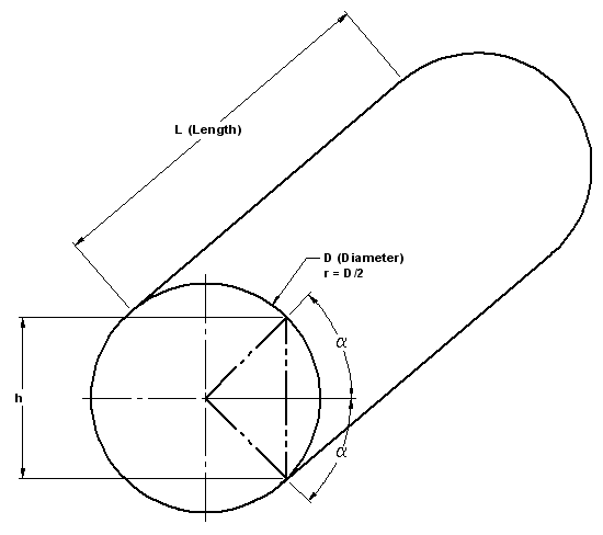
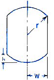
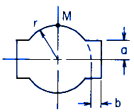
Torsional Deformation and Stress Circular shaft
with opposite sides flattened Equations
and Calculator. |
|
|
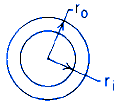
Torsional Deformation and Stress Concentric
Circular Section Equations and Calculator.
Torsional deflection and stress of a pipe. |
|
|
Torsional Deformation and Stress Eccentric Hollow
Circular Section Equations and Calculator |
|
|
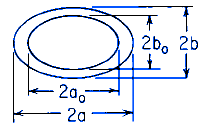
Torsional Deformation and Stress Hollow Elliptical
Section Equations and Calculator |
|
|
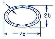
Torsional Deformation and Stress Elliptical
Hollow thin-walled section of uniform thickness
Equations and Calculator |
|
|
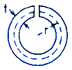
Torsional Deformation and Stress Thin Circular
Open Tube of Uniform Thickness Section Equations
and Calculator |
|
|
Torsional Deformation and Stress Any Thin Open
Tube of Uniform Thickness Calculator |
|
|
Torsion Applied Deformation and Stress of any
elongated section with axis of symmetry
OX; Equations and Calculator |
|
|
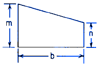
Torque Applied Deformation and Stress of a Trapezoid
Equations and Calculator |
|
|
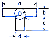
Torque Applied Deformation and Stress of a T-Section
Equations and Calculator |
|
|
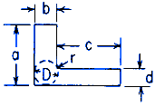
Torque Applied Deformation and Stress of a L-Section
Equations and Calculator |
|
|
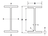
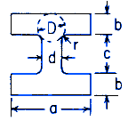
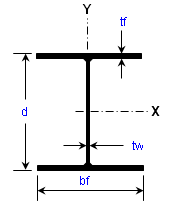
Torque Applied Deformation and Stress of a I
Beam Section Equations and Calculator
|
|
|
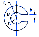
Torque Applied Deformation and Stress of a C
Beam Section Calculator |
|
|
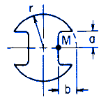
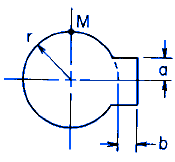
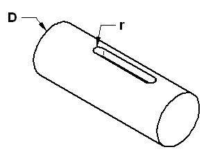
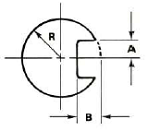
Torque Applied Deformation and Stress of a Shaft
with Keyway Equations and Calculator |
|
|
Torque Applied Deformation and Stress of a Shaft
with Two Keyway's Equations and Calculator |
|
|
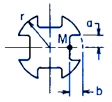
Torque Applied Deformation and Stress of a Shaft
with Four Keyway's Equations and Calculator |
|
|
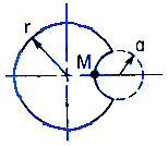
Torque Applied Deformation and Stress of a Shaft
with One Spline Equations and Calculator |
|
|
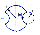
Torque Applied Deformation and Stress of a Shaft
with Two Splines Equations and Calculator |
|
|
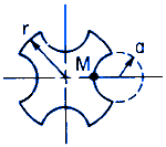
Torque Applied Deformation and Stress of a Shaft
with Four Splines Equations and Calculator |
|
|
Torque Applied Deformation and Stress of a Pinned
Shaft Equations and Calculator |
|
|
Torque Applied Deformation and Stress of a Two
Grooved Pinned Shaft Equations and Calculator |
|
|
Torque Applied Deformation and Stress of a Four
Grooved Pinned Shaft Equations and Calculator |
|
|
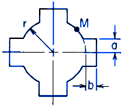
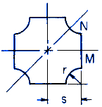
Torsional Deformation and Stress of a Cross
Shaft Equations and Calculator |
|
|
|
|
|
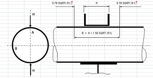
Pipe Stress due to Clamping Force Spreadsheet
Calculator
This spreadsheet calculates the a variety
of resultant engineering requirements per. Roark's
Formulas for Stress and Strain, 7th edition,
Table 9.2 Case 1, Pressure Vessel Design Manual,
3rd Edition, ASME B31.1-2006
|
|
|
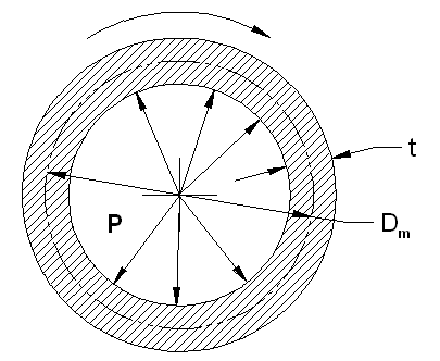
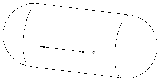
Thin
Wall Pressure Vessel Hoop Stress Hoop
stress is twice that of the longitudinal
stress for a thin wall pressure vessel.
Therefore, the Hoop stress should be the
driving design stress.
|
|
|
|
|
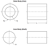
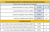
Solid Shaft Equivalent of Hollow Shaft of Same Length Equal Strength Formula and Calculator |
|
|
|
|
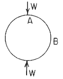
Circular Ring Moment, Hoop Load, and Radial
Shear Equations and Calculator. Loading
W applied at 180° through center of circular
section |
|
|
|
|
|
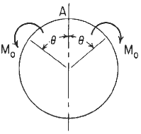
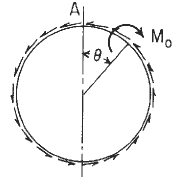
Circular Ring Moment, Hoop Load, and Radial
Shear Equations and Calculator #3.
Loading
moment applied Mo at θ relative
to x angle. Per. Roark's Formulas for Stress
and Strain Formulas for Circular Rings Section
9, Reference, loading, and load terms #3.
Formulas for moments, loads, and deformations
and some selected numerical values. |
|
|
|
|
|
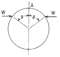
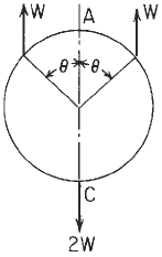
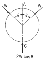
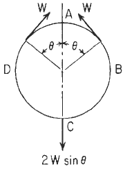
Circular Ring Moment, Hoop Load, and Radial
Shear Equations and Calculator #5.
Loading
W at θ relative to A-C Per. Roark's Formulas
for Stress and Strain Formulas for Circular
Rings Section 9, Reference, loading, and load
terms #5. |
|
|
|
|
|
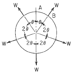
Circular Ring Moment, Hoop Load, and Radial
Shear Equations and Calculator #7. Ring
under any number of equal radial forces equally
spaced. Per. Roark's Formulas for Stress and
Strain Formulas for Circular Rings Section 9,
Reference, loading, and load terms #7. Formulas
for moments, loads, and deformations and some
selected numerical values. |
|
|
|
|
|
|
|
|
Circular Ring Moment, Hoop Load, and Radial
Shear Equations and Calculator #10 Per.
Roark's Formulas for Stress and Strain Formulas
for Circular Rings Section 9, Reference, loading,
and load terms #10. Formulas for moments, loads,
and deformations and some selected numerical
values.
|
|
|
Circular Ring Moment, Hoop Load, and Radial
Shear Equations and Calculator #11. Per.
Roark's Formulas for Stress and Strain Formulas
for Circular Rings Section 9, Reference, loading,
and load terms #11. Formulas for moments, loads,
and deformations and some selected numerical
values. |
|
|
|
|
|
|
|
|
Circular Ring Moment, Hoop Load, and Radial
Shear Equations and Calculator #14. Per.
Roark's Formulas for Stress and Strain Formulas
for Circular Rings Section 9, Reference, loading,
and load terms #14. Formulas for moments, loads,
and deformations and some selected numerical
values. |
|
|
Circular Ring Analysis No 15 Roark's Formulas
for Stress and Strain Equations and Calculator
Per. Roark's Formulas for Stress and Strain
Formulas for Circular Rings Section 9, Reference,
loading, and load terms Formulas for moments,
loads, and deformations and some selected numerical
values. |
|
|
Circular Ring Analysis No 16 Roark's Formulas
for Stress and Strain Equations and Calculator.
Per. Roark's Formulas for Stress and Strain Formulas
for Circular Rings Section 9, Reference, loading,
and load terms.
Formulas for moments, loads, and deformations
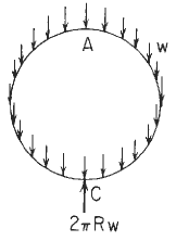
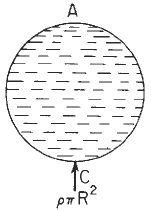
and some selected numerical values. Unit axial
segment of pipe filled with liquid of weight
per unit volume ρ and supported at the base. |
|
|
Circular Ring Moment, Hoop Load, and Radial
Shear Equations and Calculator #17. Per.
Roark's Formulas for Stress and Strain Formulas
for Circular Rings Section 9, Reference, loading,
and load terms. Formulas for moments, loads,
and deformations and some selected numerical
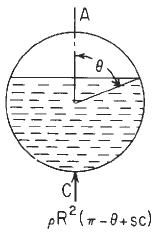
values. Unit axial segment of pipe partly filled
with liquid of weight per unit volume ρ
and supported at the base. |
|
|
Circular Ring Moment, Hoop Load, and Radial
Shear Equations and Calculator #18 Per.
Roark's Formulas for Stress and Strain Formulas
for Circular Rings Section 9, Reference, loading,
and load terms. Formulas for moments, loads,
and deformations and some selected numerical
values. |
|
|
|
|
|
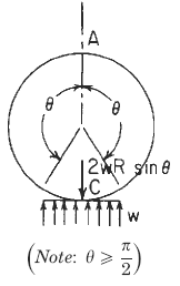
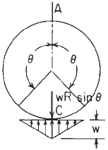
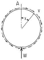
Circular Ring Moment, Hoop Load, and Radial
Shear Equations and Calculator #20. Per.
Roark's Formulas for Stress and Strain Formulas
Section 9, Reference, loading, and load terms
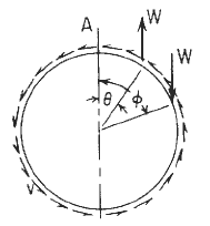
#20. Bulkhead or supporting ring in pipe, supported
at bottom and carrying total load W transferred
by tangential shear v distributed as shown. |
|
|
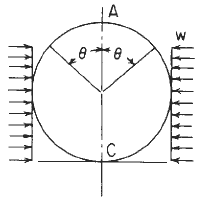
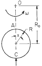
Circular Ring Moment, Hoop Load, and Radial
Shear Equations and Calculator #21 Per.
Roark's Formulas for Stress and Strain Formulas
for Circular Rings Section 9, Reference,
loading, and load terms. Formulas for moments,
loads, and deformations and some selected
numerical values. Ring rotating at angular
rate ω rad/s about an axis perpendicular
to the plane of the ring. Note the requirement
of symmetry of the cross section.
|
|
|
|
|
|
Punching Shear/Conductor Modification Analysis
|
|
|
|
|
|
Power Transmission Shaft Design Formulas and
Calculator for Torsional Stress, Deflection Calculator for Stress and Tensile or Compressive Stress.
|
|
|
The Shaft Design Book (Design Charts and
Calculations for Torsional Properties of Non-Circular
Shafts) Premium Membership Required |
|
|
|
|
|
|
|
|
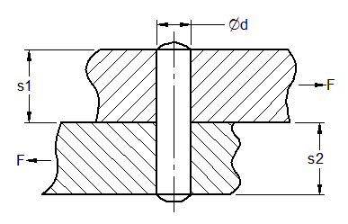
Dowel Pin Design Length Shear Stress and Contact
Pressure Check Equations and Calculator |
|
|
|
|
|
|
|
|
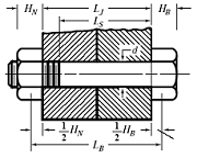
Bolt Elongation Equation and Calculator while
under Axial Stress |
|
|
Method and Equations of Analysis BS449: Part
2 |
|
|
Bearing Strength of a Pin in a Drilled Hole
Spreadsheet Calculator |
|
|
Analysis of Stress and Deformation, George
W. Housner, Thad Vreeland, Jr., Division of
Engineering and Applied Science, California
Institute
447 Pages Premium Membership Required
|
|
|
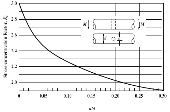
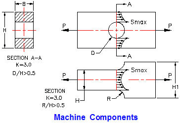
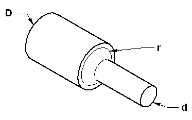
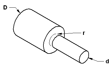
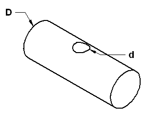
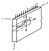
Stress Concentration Factors for Flat Plates
and Cylinders: In a structure or machine
part having a notch or any abrupt change in
cross section, the maximum stress will occur
at this location and will be greater than the
stress calculated by elementary formulas based
upon simplified assumptions as to the stress
distribution.
|
|
|
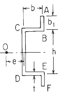
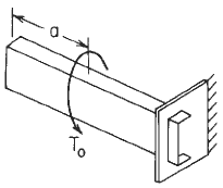
Channel Section with Concentrated Intermediate
Torque applied Deflection and Stress Equations
and Calculator #1a. Formulas for the elastic
deformations of uniform thin-walled open members
under torsional loading. Per. Roark's Formulas
for Stress and Strain - Formulas for torsional
properties and stresses in thin-walled open
cross sections, Table 10.2.
|
|
|
C-Section with Concentrated Intermediate Torque
applied Deflection and Stress Equations and
Calculator #2 of 1a Loading. Formulas for
the elastic deformations of uniform thin-walled
open members under torsional loading. Per. Roark's Formulas
for Stress and Strain - Formulas for torsional
properties and stresses in thin-walled open
cross sections, Table 10.2.
|
|
|
|
|
|
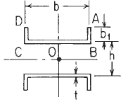
Twin Channel With Flanges Inward Section with
Concentrated Intermediate Torque applied Deflection
and Stress Equations and Calculator #4 of 1a
Loading. Formulas for the elastic deformations
of uniform thin-walled open members under torsional
loading. Per. Roark's Formulas for Stress and
Strain - Formulas for torsional properties and
stresses in thin-walled open cross sections,
Table 10.2. |
|
|
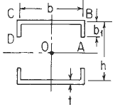
Twin Channel With Flanges Outward Section with
Concentrated Intermediate Torque applied Deflection
and Stress Equations and Calculator #5 of 1a
Loading. Formulas for the elastic deformations
of uniform thin-walled open members under torsional
loading. Per. Roark's Formulas for Stress and
Strain - Formulas for torsional properties and
stresses in thin-walled open cross sections,
Table 10.2. |
 |
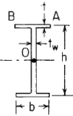
Wide Flange with Equal Flanges Section with
Concentrated Intermediate Torque applied Deflection
and Stress Equations and Calculator #6 of 1a
Loading. Formulas for the elastic deformations
of uniform thin-walled open members under torsional
loading. |
|
|
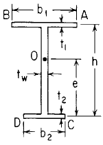
Wide Flange Beam with Unequal Flanges Section
with Concentrated Intermediate Torque applied
Deflection and Stress Equations and Calculator
#7 of 1a Loading. Formulas for the elastic
deformations of uniform thin-walled open members
under torsional loading. Per. Roark's Formulas
for Stress and Strain - Formulas for torsional
properties and stresses in thin-walled open
cross sections, Table 10.2.
|
 |
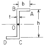
Z-Section Flange Beam with Concentrated Intermediate
Torsional Loading Applied Deflection and Stress
Equations and Calculator #8 of 1a Loading.
Formulas for the elastic deformations of uniform
thin-walled open members under torsional loading.
Per. Roark's Formulas forStress and Strain -
Formulas for torsional properties and stresses
in thin-walled open cross sections, Table 10.2.
|
 |
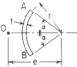
Segment of a Circular Tube Beam with Concentrated
Intermediate Torsional Loading Applied Deflection
and Stress Equations and Calculator #9 of 1a
Loading. Formulas for the elastic deformations
of uniform thin-walled open members under torsional
loading. Per. Roark's Formulas forStress and
Strain - Formulas for torsional properties and
stresses in thin-walled open cross sections,
Table 10.2, Row 9.
|
 |
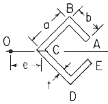
Missing Segment Rectangular Tube Section with
Concentrated Intermediate Torsional Loading
Applied Deflection and Stress Equations and
Calculator #10 of 1a Loading. Formulas for
the elastic deformations of uniform thin-walled
open members under torsional loading. Per. Roark's Formulas
for Stress and Strain - Formulas for torsional
properties and stresses in thin-walled open
cross sections, Table 10.2, Row 10.
|
 |
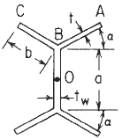
Double Y Section with Concentrated Intermediate
Torsional Loading Applied Deflection and Stress
Equations and Calculator #11 of 1a Loading.
Formulas for the elastic deformations of uniform
thin-walled open members under torsional loading.
Per. Roark's Formulas for Stress and Strain
- Formulas for torsional properties and stresses
in thin-walled open cross sections, Table 10.2,
Row 11.
|
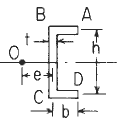
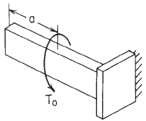 |
Channel Section with Left end free to twist
and warp right end fixed (no twist or warp)
Deflection and Stress Equations and Calculator.
Formulas for the elastic deformations of uniform
thin-walled open members under torsional loading.
Per. Roark's Formulas for Stress and Strain
- Formulas for torsional properties and stresses
in thin-walled open cross sections, Table 10.2,
Loading Configuration 1b.
|
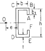
 |
C-Section with Concentrated Intermediate Torque
applied Deflection and Stress Equations and
Calculator #2 of 1b Loading .
Formulas for the elastic deformations of uniform
thin-walled open members under torsional loading.
Per. Roark's Formulas forStress and Strain
- Formulas for torsional properties and stresses
in thin-walled open cross sections, Table 10.2.
|
|
|
Stress Analysis Manual Premium Membership
Required |
 |
Beam Deflection and Stress Excel Spreadsheet
Calculator - Premium (annual) membership
required |
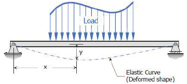 |
Double Integration Method for Beam Deflections
Overview
The Double Integration Method, also known
as Macaulay’s Method is a powerful tool
in solving deflection and slope of a beam at
any point
|
 |
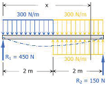
Double Integration Method Example 1 Simply Supported
Beam with Concentrated Load at Mid Span |
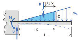 |
Double Integration Method Example 3 Proof Cantilevered
Beam of Length L with Variable Increasing
Load to ωo at free end.
|
 |
|
|
|
|
 |
Deflection and Stresses in Uniformly Loaded,
Simply Supported, Rectangular Sandwich plate
- Premium membership required |
 |
Deflection of a Circular Sandwich Plate by Load
Applied Through an Insert - Premium membership
required |
 |
Metal Fatigue Engineering Analysis Excel Spreadsheet
Calculator Note: Accessing this
resource requires an active
Premium Annual Membership
with Engineers Edge |
 |
|
 |
Misc Stress and Design Applications
|
|
Torsional Rigidity of Cantilever Wings with Constant Spar and Rib Sections |


