Related Resources: calculators
Channel Section with Left End Free to Twist Right End Fixed Equations and Calculator
Channel Section with Left end free to twist and warp right end fixed (no twist or warp) Deflection and Stress Equations and Calculator.
Formulas for the elastic deformations of uniform thin-walled open members under torsional loading.
Per. Roarks Formulas for Stress and Strain - Formulas for torsional properties and stresses in thin-walled open cross sections, Table 10.2, Loading Configuration 1b.
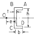
Section Dimensional Definitions
Figure 1
Loading configuration left end free to twist and warp right end fixed (notwist or warp)
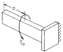
Figure 2
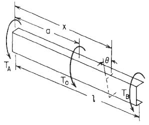
Concentrated intermediate torque of Channel Beam Orientation Declarations Image
Figure 3
Preview: Channel section thin wall stress and torsional properties #1b calculator
Channel Section Properties Constants Formulas See: Figure 1
![]()
![]()
![]()
Selected maximum values of stress and torsion
![]()
throughout the thickness at corners A and D
 |
throughout the thickness at a distance
from corners A and D |
![]()
Left end free to twist and warp, right end free to warp but not twist Formulas:
Boundary values for Loading condition See Figure 2
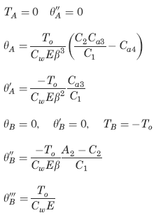
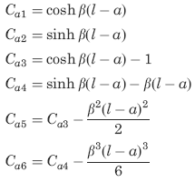
The following constants and functions are hereby defined in order to permit condensing the tabulated formulas which follow.
Concentrated intermediate torque See Figure 3
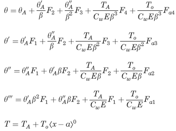
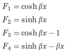
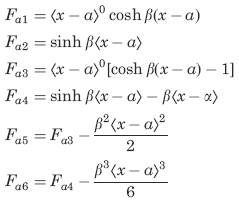
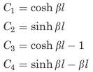
![]()
Where (when used in equations and this calculator):
Point 0 indicates the shear center se "Concentrated intermediate torque of Channel Beam Orientation Declarations image ";
e = distance from a reference to the shear center (in, m);
K = torsional stiffness constant (in4, m4);
C =warping constant (in6, m6);
τ1 = shear stress due to torsional rigidity of the cross section (lbsf/in2, m2);
τ2 = shear stress due to warping rigidity of the cross section (lbsf/in2, m2);
σx = bending stress due to warping rigidity of the cross section (lbsf/in2, m2);
E = modulus of elasticity (lbs/in2, m2);
G = modulus of rigidity (shear modulus) of the material (lbs/in2, m2)
To = applied torsional load (in-lbs, N-m);
to = applied distributed torsional load (lbsf/in, N/m);
TA and TB are the reaction end torques at the left and right ends, respectively (in-lbs, N-m);
θ = angle of rotation at a distance x from the left end (radians).
θ', θ'', θ''', = are the successive derivatives of y with respect to the distance x.
Cw = the warping constant for the cross section;
All rotations, applied torsional loads, and reaction end torques are positive as shown (CCW when viewed from the right end of the member)
Unit step function defined by use of ⟨ ⟩
⟨ x - θ ⟩0
if x < a, ⟨ x - a ⟩n =0;
if x > a, ( x - a) n ;
The function sinh β
β = ( KG/CwE)1/2
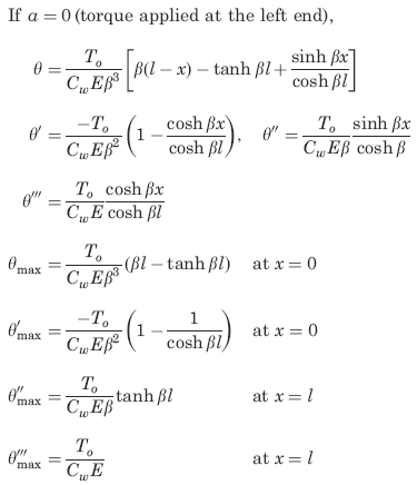
Supplemental selected special cases and maximum values (not included in calculator), See Figure 2.
Reference:
Roarks Formulas for Stress and Strain, 7th Edition, Table 10.2 and 10.3 Loading Configuration 1b. Formulas for torsional properties and stresses in thin-walled open cross sections.