Related Resources: calculators
Compressible Flow through a Constriction Equations and Calculator
Compressible Flow through a Constriction Equations and Calculator
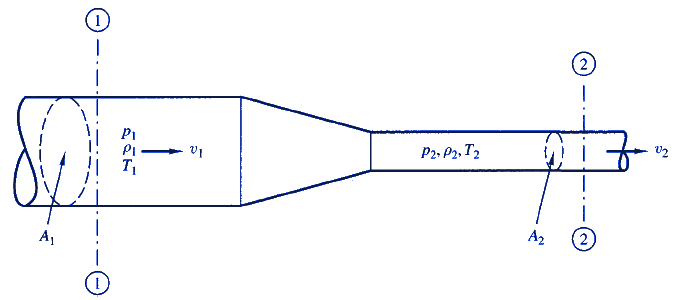
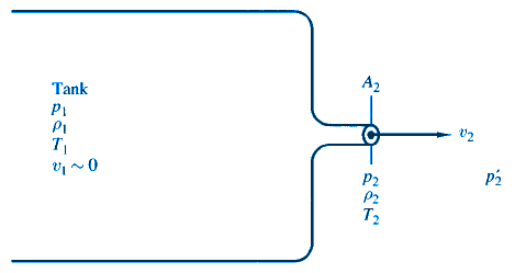
Figure 1 depicts compressible fluid flow through a constriction in a conduit. The various parameters are shown at point 1 in the larger section and point 2 in the smaller section. This configuration is similar to the convergent nozzle (Fig. 2), but it differs because the cross section at point 1 is generally not large enough to neglect velocity v1.

Figure 1, Compressible flow through a constriction.
Preview Compressible Flow through a Constriction Calculator
The weight flow rate for compressible flow through a constriction can be determined from the equation
Eq. 1
Eq. 2
where
G = weight flow rate, lbs/ft2, (N/m2)
d1 = inlet area diameter, ft, (m)
d2 = inlet area diameter, ft, (m)
A1 = inlet area, ft2, (m2)
A2 = constriction area, ft2, (m2)
g = acceleration of gravity, ft/sec2 (m/sec2)
k = specific heat ratio
p1 = pressure inside the tank, lbs/ft2, (N/m2)
p2 = pressure inside the tank, lbs/ft2, (N/m2)
γ1 = specific weight of fluid inside the tank, lbs/ft3, (N/m3)
R = Gas constant, ft/°R, (m/K)
Schaum's Outline of Fluid Mechanics and Hydraulics
Related
- Flow through Convergent Nozzle Equations and Calculator
- Convergent Divergent Nozzle Flow Velocity and Area Equation and Calculator
- Isentropic Flow of Fluid Equations and Calculator
- Isentropic Flow Relationships
- Isentropic Process Thermodynamic
- Isentropic Pressure and Volume
- Calculation of Mass Flow Rate Equation
- Mass Flow Rate Fluids Flow Equation
- Convergent Nozzle Flow Velocity and Area Equation and Calculator
- Continuity Equation Fluids Flow
- Convergent-Divergent Nozzle Flow Velocity and Area Equation and Calculator
- Viscosity of Fluid with Falling Sphere at Terminal Velocity Equation and Calculator Measurement of Viscosity in a Vertical Falling Ball Viscometer Calculator
- Pitot-Static Tube Velocity of Fluid Flow Measurement Calculator and Equation
- Velocity of Water Due To Head in Feet Table
- Conservation of Mass Fluids - Fluid Flow Hydraulic and Pneumatic
- Velocity of Escaping Compressed Air Equation and Calculator
- Total Head Pressure Velocity Equations and Calculator
- Pipe Whip If a pipe were to rupture, the reaction force created by the high velocity fluid jet could cause the piping to displace and cause extensive damage
- Fluid Flow Open Channel Calculator Chezy and Manning's equation to determine the wetted perimeter, hydraulic radius, flow area, Chezy coefficient and flow velocity
- Flow Velocity Profiles Not all fluid particles travel at the same velocity within a pipe.
- Average (Bulk) Velocity Ia single average velocity to represent the velocity of all fluid at that point in the pipe.
- Compressibility of a Fluid Equations and Calculator
- Compressibility of Liquids Equations and Calculators
- Flow Through a Sluice Gate Formula and Calculator
