Related Resources: calculators
Compression Buckling in Unstiffened Plates Formula and Calculator
Unstiffened Plates in Compression Buckling Formula and Calculator
Figure 1a shows buckling of a plate free along two edges. When loaded in axial compression, the plate will want to expand in the transverse direction. If the supports restrain sideways movement, lateral stress will develop. According to Hooke’s law (1678), in an element subjected to stresses in both the x and y directions (σx and σy) is
Eq. 1
Figure 1
Coordinate system and buckling modes. (a) Free on two edges, (b) simply supported on
four edges and (c) simply supported on four edges.
It can be shown that the elastic critical buckling stress for the plate shown in Figure a is
Eq. 2
Equation 2 is the same as the Euler elastic critical buckling stress equation for a simply supported rectangular strut , except for the term 1−ν2, which has the effect of increasing σcr by 10% for steel plates. For the more useful case of a plate simply supported on all four edges (Figure 1b and c), the solution becomes
Eq. 3
For steel, ν = 0.3, E = 210,000 N/mm2 and Equation 3 becomes
Eq. 4
which solves to
Eq. 5
It is important to realise that the buckling stress for a plate free on two edges (Figure1a) is dependent on the length (a), whereas for a plate restrained on four edges (Figure 1b and c), it is dependent on width (b). This is illustrated by Figure 1c, which shows a plate twice as long as that in Figure 1b. Since the width of both plates is identical, the elastic critical buckling stress is unaffected despite the increased length. This dependency on width rather than length means that longitudinal stiffeners are far more effective than transverse ones.
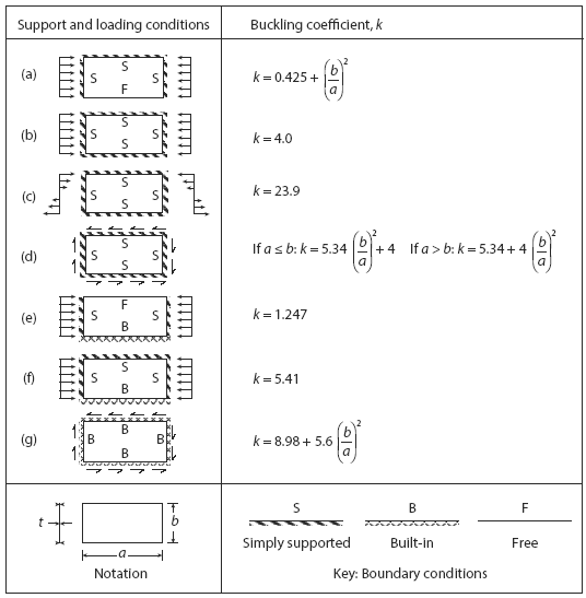
The factor k in Equation 5 is known as the buckling coefficient, which for a plate simply supported on all four edges and loaded in uniform compression (Figure 1b and c) is never less than 4.0. Figure 2 itemises buckling coefficients for a range of different plate types and loadings. For example, Figure 2c shows that k equals 23.9, for a plate simply supported on four edges and subjected to a bending stress distribution.

Figure 2 Buckling coefficients for unstiffened plates.
where
ν is Poisson’s ratio.
E is Young’s modulus.
σcr is the elastic critical buckling stress.
t is the plate thickness.
a is the plate length.
E is the Modulus of elasticity
k is the buckling coefficient.
b is the plate width (height) (see Figure 2).
t is the plate thickness.
Simplification of the Mcr formula. In most practical situations, C makes little difference to strength. Therefore, in the interests of simplicity, it can be set as equal to 1.0 for all end conditions and therefore eliminated from the design process. In addition, the resistance to warping at the ends of the beam can also be neglected with only a slight loss of efficiency. These changes lead to the following simpler expression:
Design strength. The elastic critical buckling compression stresses define the theoretical upper limit on strength. In practice, yielding and weld shrinkage stresses, as well as lack of straightness, all combine to reduce strength. The codes of practice have a variety of semi-empirical methods to account for these defects. These can be complex, but an approximation for the design value of buckling stress (σRd) can be made using a Gordon–Rankine type approximation, i.e.,
Eq. 6
which rearranges to
Eq. 7
where
σRd is the design value for the buckling stress.
σy is the yield stress.
Design procedure. The first step is to identify the appropriate buckling coefficient from Figure 2, which applies to the particular plate concerned. The plate length (a) and width (b) are defined by the distance between plates connected at right angles. The boundaries are usually either free or simply supported. The next step is to determine the elastic critical buckling stress and, finally, the design value of the buckling stress, using Equation 8. An efficient design will achieve buckling stresses close to the yield value. If this is not the case, then stiffeners are added.
Source:
- Structural Design First Principles, Michael Byfield
Related
- Steel Beam and Column Analysis and Code Check Calculator
- Buckling of Flat Plates Excel Calculator
- Buckling of Foam Core Sandwich Panels Excel Calculator
- Plate Shear Buckling Stress Formulae and Calculator
- Nonlinear Buckling of Cylinder under External Lateral Pressure
- Buckling of Curved Plates
- Ideal Pinned Column Buckling Equation and Calculation, Euler's Formula
- Buckling of Cylinder Plate Equations and Calculation
- Buckling of Uncored Composite Panels Excel Calculator
- Rankine Gordon Equation
- Buckling of a rectangular column on the basis of Murnaghan's formula for strain energy
- Bar Restrained Against Lengthwise Thermal Expansion Calculator and Equations
- Bar Restrained Against Lengthwise Thermal Expansion Calculator and Equations
- Bar Restrained Against One End and Gap on Other Stress and Force Calculator and Equations
- Bar Restrained With Spring Uniform Heat Applied Calculator
- Two Bars At Different Temperatures Stress Calculator and Equations
- Lateral Torsional Buckling Formulae and Calculator
- Buckling Rectangular Column