Related Resources: calculators
Cross Shaft Torsional Deflection, Stress Equation and Calculator
Beam Deflection and Stress Equation and Calculators
Torsional Deformation and Stress of a Cross Shaft Equations and Calculator

ALL calculators require a Premium Membership
Preview
Torque Applied Deformation and Stress of a Cross Shaft Section Calculator
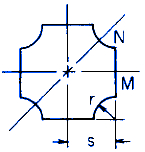
K = 2Cs4
Varies with s / r as follows
For:
0 ≤ r / s ≤ 0.9
![]()
Angle of Twist under applied Torque Moment
θ = ( T L ) / ( K G )
Shear Stress Maximum
At M Location:
![]()
Where BM varies with r / s as follows:
for 0.1 ≤ r / s ≤ 0.5
![]()
At N Location:
![]()
Where BN varies with r / s as follows:
for 0.3≤ r / s ≤ 0.9
![]()
Note: BN > BM for r / s > 0.32
Where:
θ = angle of twist (radians),
T = Twisting or torque moment force-length, (in-lbs, N-mm),
L = Length of Section (in, mm),
h = Length as Indicated (in, mm),
r, s = Dimension as Indicated (in, mm),
τ = Unit shear stress force / area (lbs/in2, N/mm2),
G = Modulus of rigidity force / area (lbs/in2, N/mm2),
K = Polar Moment of Inertia (in4, mm4) for section
Reference:
Roarks Formulas for Stress and Strain, 7th Edition, Table 10.1 Formulas for torsional deformation and stress.
Related:
The Shaft Design Book (Design Charts and Calculations for Torsional Properties of Non-Circular Shafts)