Related Resources: calculators
Curved I-Beam Stress Formulas and Calculator
Beam Deflection and Stress Calculators with Formulas
Curved I-Beam Stress Formulas and Calculator
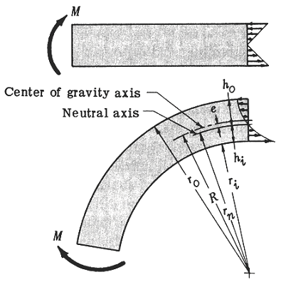
Bending stresses in curved beams do not follow the same linear variation as straight beams, because of the variation in arc length. Even though the same assumptions are used for both types, i.e. that plane section perpendicular to the axis of the beam remain plane after bending and that stress is quite different. Figure 1.0 shows the linear stress variation in a straight beam and the hyperbolic stress distribution in a curved beam. Note that the bending stress in the curved beam is zero at a point other than at the center of gravity axis. Also, note that the neutral axis is located between the gravity axis and the center of curvature: this always occurs in curved beams.
Preview Curved I-Beam Stress Calculator

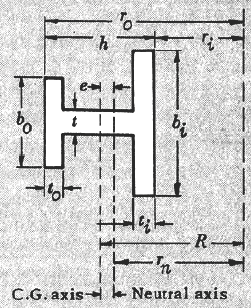
Figure 2.0 I-Beam Dimensions
Stress Distribution due to bending is given by:
Equation 1
s = M · γ / ( A · e · ( rn - y ) )
Where:
s = the bending stress, psi
M = bending moment with respect to the centroical axis, in-lb
y = distance from the neutral axis to the point in question, inches (positive for distances toward the center of curvature, negative for distances away from the center of curvature)
A = the area of the section, in2
e = distance from the center of gravity axis to the neutral axis, inches
rn = radius of curvature of the neutral axis, inches
value of e used for base log = 2.7182818
Bending Stress at the Inside Fiber is given by:
Equation 2
s = ( M · hi ) / ( A · e · ri )
Where:
hi = distance from the center neutral axis to the inside fiber, inches ( hi = rn - ri )
ri = radius of curvature on the inside fiber, inches
Bending Stress at the Outside Fiber is given by:
Equation 3
s = ( M · ho ) / ( A · e · ri )
Where:
ho = distance from the center neutral axis to the inside fiber, inches ( ho
= ro - ri )
ro = radius of curvature on the outside fiber, inches
A = bi ti + bo to + (h - ti - to ) t
I-Beam Stuctural shape
rn = [ ( bi - t ) ti + ( bo - t ) (to ) + th ] / [ i loge ( ( ri + ti ) / ri ) + t loge ( ( ro - to ) / ( ri + ti ) )+ bo loge ( ro / ( ro - to ) )]
e = R - rn
R = ri + [ (1/2) h2 t + (1/2) ti2 ( bi - t ) + ( bo - t ) ( to ) ( h - (1/2) to ) ( h - (1/2) to ] / [ ( bi - t ) ( ti ) + ( bo - t ) ( to ) - th ]
Where:
bi = I-beam flange width, in
bo = I-beam flange thickness, in
ti = flange web thickness, in
to = flange web thickness, in
ti = flange web thickness, in
h
= flange web thickness, in
Related:
- Curved Circular Beam Stress Formulas and Calculator
- Curved Rectangular Beam Stress Formulas and Calculator
- Curved Beam Stress Deflection Design Spreadsheet Calculator
- Strength of Materials Basics and Equations | Mechanics of Materials
- Civil Engineering Design Knowledge
- Double Integration Method for Beam Deflections
- Double Integration Method Example 5 Proof Pinned Supported Beam
- Bending, Deflection and Stress Equations Calculator for Beam Fixed at One End, Supported at the Other, Load at Center
References:
- McGraw Hill Machine Design (1968)
