Related Resources: calculators
Helical Spring Fatigue Loading and Factor of Safety Formulas and Calculator
Helical Spring Fatigue Loading and Factor of Safety Formula and Calculator
Rarely are helical springs not subjected to fatigue loading. The number of cycles may only be in hundreds or thousands, but usually they must be designed for millions and millions of cycles such that an infinite life is desired.
Helical springs may be subjected to completely reversed loading, where the mean shear stress (τm) is zero; however, as this type of spring is installed with a preload, the spring is usually subjected to fluctuating loading. The fluctuating loading may be compressive or tensile, but never both.
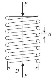
If the maximum force on the spring is denoted as (Fmax) and the minimum force is denoted as (Fmin), whether they are compressive or tensile, then the mean force (Fm) and alternating force (Fa) are given by the relationships in Eqs. 1 and 2.

Helical Compression Spring
Preview Helical Spring Fatigue Loading and Factor of Safety Calculator
Mean spring force
Eq 1
Fm = ( Fmax + Fmin ) / 2
Alternating spring force
Eq. 2
Fa = ( Fmax - Fmin ) / 2
Stress-concentration factors are applied only to the alternating stresses the mean shear stress (τm) is given by:
Eq. 3
τm = Ks ( 8 Fm D ) / ( π d3 )
where is the shear-stress correction factor
Eq. 4
Ks = 1 / ( 2 C ) + 1 = ( 1 + 2 C ) / ( 2 C )
and
C = D / d ≤ C ≤ 12
Using the Bergstrasser factor ( KB ) in place of the shear-stress correction factor ( Ks ), the alternating shear stress ( τa ) is:
Eq. 5
τa = KB ( 8 Fa D ) / ( π d3 )
and
KB = ( 4C + 2 ) / ( 4C -3)
Also, the Goodman theory for fluctuating torsional loading is applicable where the factor of safety (n) for a safe design was given by:
Eq. 6
(Goodman Theory)
τa / Se + τa / Sus = 1 / n
where the endurance limit (Se) is calculated as usual using the Marin formula with the load type factor (kc) equal to (0.577), and the ultimate shear stress ( Sus ) found from the relationship:
Eq. 7
Sus = ( 0.67 ) Sut
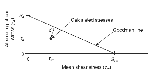
The Goodman theory given in Eq. (6) can be represented graphically as:
The perpendicular distance (d) to the Goodman line in Fig. 2 represents how close the factor-of-safety (n) is to the value of 1.
Once the mean shear stress (τm), the alternating shear stress (τa), the endurance limit (Se), and the ultimate shear strength (Sus) are known, the factor-of-safety (n) for the design can be determined either mathematically using Eq. 8) or graphically using figure 2.
Factor of safety
Eq. 8
τa / Se + τm / Sus = 1 / n
Where:
Fmin = minimum force on the spring (lb, N)
Fmaxmax = maximum force on the spring (lb, N)
D = spring coil mean diameter ( in, m )
d = section diameter ( in, m )
Se = endurance limit (kpsi, MPa)
Sus = ultimate shear stress(kpsi, MPa)
Related:
- Helical Compression Spring Critical Frequency Formula and Calculator
- Spring Terminology and Definitions
- Belleville Spring Washer Equation and Calculator
- Spring Types and Materials Review
- Morrison's Spring Tables Design Reference
- Leaf Spring Design and Engineering Strength of Materials
- Coil Spring Engineering Design Application
- Helical Compression Spring Design Equations and Calculator
- Compression Spring Assembly Operating Life and Reliability Equations and Calculator
- Shock Loading Helical Springs Formulas and Calculator
Source:
Mark's Calculations for Machine Design
Thomas H. Brown, Jr.
Faculty Associate
Institute for Transportation Research and Education
NC State University
Raleigh, North Carolina
