Related Resources: calculators
Overall Heat Leakage Coefficient Equation and Calculator
Heat Transfer Engineering Design
Overall Heat Leakage Coefficient Test Procedure, Equation and Calculator
Heat Leakage Test requirements Refrigeration System Design Equations and Calculator
Per. MIL-PRF-32017
Heat leakage test. The system shall have a minimum clearance of 5 feet between the surrounding room walls. The overall heat leakage shall be determined as follows:
a. An electric fan, of sufficient capacity to insure that no uncirculated air pocket will exist, shall be installed inside the IC. The electrical energy of the fan motor shall be measured by watt- hour meter with a scale of 0.1 kilowatt-hour or less and this heat equivalent shall be added to other sources of heat added to the IC.
b. Four thermocouples, shielded from the effects of radiant heat, shall be installed inside the IC and positioned within 6 inches of the ceiling and floor at two opposite corners. The interior temperature shall be taken as the average of the four thermocouples.
c. Heating elements shall be installed approximately in the center of the IC. Electrical heat input shall be measured by a watt-hour meter with a scale increment of 0.1 kilowatt-hour or less.
d. Eight thermometers or thermocouples, shielded from the effects of radiant heat, shall be installed approximately 18 inches from each corner of the IC in the room where it is placed. The ambient temperature shall be taken as an average of these eight thermocouple readings.
e. All openings in the IC shall be sealed, and the IC shall remain undisturbed throughout the test.f. The ambient temperature shall then be maintained constant within ± 2°F. Sufficient, steady,
non-varying heat shall be added to the interior of the IC to maintain a minimum of 60°F and a maximum of 100°F temperature difference between the interior and exterior of the IC.
g. The test shall be considered concluded when eight consecutive half-hourly readings indicate that:
1. The ambient temperature has been maintained constant within ± 2°F.
2. The temperature inside the IC has been maintained constant within ± 1°F.

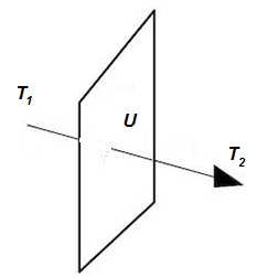
h. The overall heat leakage coefficient U of the IC is given by:
![]()
H1 = Sum of all electrical heat energies added to the IC (Btu/hr)
T1 = Average interior temperature of the IC (100°F to 155°F)
T2 = Average ambient temperature (60°F to 100°F)
Preview: Overall Heat Leakage Coefficient Calculator (Membership Required: Premium).
i. The heat leakage coefficient shall be 15 Btu/hr/°F or less.
Note: this is a military specification, commercial application requirements can be different.