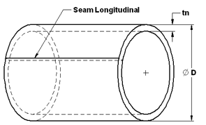
Pressure Vessel Pipe Stress Longitudinal Stress (Circumferential Joint)
Pressure Vessel Design and Calculators
Longitudinal Stress (Circumferential Joint). When the thickness does not exceed one-half of the inside radius, or P does not exceed 1.25SE, the following formulas shall apply:
This calculator and associated formulas will govern only when the circumferential joint efficiency is less than one-half the longitudinal joint efficiency, or when the effect of supplementary loadings (UG-22) causing longitudinal bending or tension in conjunction with internal pressure is being investigated. An example illustrating this investigation is given in L-2.1 and L-2.2.
Note:
Pressure Vessel Pipe Longitudinal Stress (Circumferential Joints) should be design checked as well

Wall Thickness (t)
![]()
Pressure (P)
![]()
Where:
E = joint efficiency for, or the efficiency of, appropriate joint in cylindrical or spherical shells, or the efficiency of ligaments between openings, whichever is less.
For welded vessels, use the efficiency specified in UW-12. For ligaments between openings, use the efficiency calculated by the rules given in UG-53.
P = internal design pressure (see UG-21)
R = inside radius of the shell course under consideration. (For pipe, the inside radius R is determined by the nominal outside radius minus the nominal wall thickness.)
S = maximum allowable stress value (see UG-23 and the stress limitations specified in UG-24)
t = minimum required thickness of shell
U1 = Undertolerance allowance (%) typically 12.5%
U2 = Adjusted thickness by Undertolerance (U1 x t)
nt = Nominal thickness adjusted for corrosion and undertolerance, (= t - Ca - U2)
R = Radius, (=D/2 - t)
tr = Required design thickness
References: ASME Boiler and Pressure Vessel Code
Contributed by:
Harsh Murugesan
Pune, Maharashtra India