Related Resources: calculators
Reaction and Deflection Case 5N Elastic Frame Roark's Formulas for Stress and Strain Formulas and Calc
Beam Deflection and Stress Equation and Calculators
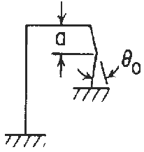
Reaction and deflection formulas for in-plane loading of elastic frame with mounting ends fixed and Concentrated Angular Displacement on the Right Vertical Member Frame formulas and calculator. Roark's Formulas for Stress and Strain, Seventh Edition, Table 8.2 reference loading number 5N.
The formulas are given for the indeterminate reactions and end deformations for a rigid frame consisting of three members. Only in-plane deformations and only those due to bending moments have been included in the expressions found in the provided formula. Since deformations due to transverse shear and axial loading are not included, the results are limited to those frames made up of members which are long in proportion to their depths.
Each member must be straight and of uniform cross section having a principal axis lying in the plane of the frame. The elastic stability of the frame, either in the plane of the frame or out of this plane, has not been treated.
Obviously the formulas are designed for frames with three members where the vertical members both lie on the same side of the horizontal member, its use is not limited to this configuration. One can set the lengths of either of the vertical members, members 1 and 2, equal to zero and solve for reactions and deformations of two-member frames. The length of the horizontal member, member 3, should not be set to zero for two reasons: (1) It does not generally represent a real problem; and (2) the lengths of members 1 and 2 are assumed not to change, and this adds a restraint to member 3 that would force it to have zero slope if its length was very short.
The formulas given assume the frames to have rigid corners; however, corrections can be made easily once the rigidity of a given corner design is known by making use of the concentrated angular displacement loading with the displacement positioned at the corner.

Loading Configuration

Left end fixed, right end fixed

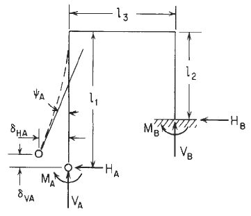
General Elastic Frame Designations
This calculator requires a Premium Membership
Deformation equations:
Horizontal deflection at A = δHA = CHHHA + CHVVA + CHMMA - LFH
Vertical deflection at A = δVA = CVHHA + CVVVA + CVMMA - LFV
Angular rotation at A = ψA = CMHHA + CMVVA CMAMA- LFM
Where:
![]()
![]()
![]()
![]()
![]()
![]()
Since δH = 0, δVA = 0, and ψA = 0, these three equations are solved simultaneously for HA, VA, and MA:

Loading terms for Concentrated moment on the right vertical member frame member:

Where used:
Δo = Displacement (in, mm),
θo = Angular Displacement (radians),
W = Load or Force (lbsf, N),
w = Unit Load or force per unit length (lbs/in, N/mm),
MA = Couple (moment) ( lbs-in, N-mm),
Mo = Couple (moment) ( lbs-in, N-mm),
θo = Externally created angular displacement (radians),
T1 - T2 = Uniform temperature rise (°F),
To = Average Temperature (deg °F),
γ = Temperature coefficient of expansion [ µinch/(in. °F), µmm/(mm. °F) ],
T1, T2 = Temperature on outside and inside respectively (degrees),
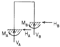
HA, HB = Horizontal end reaction moments at the left and right, respectively, and are positive clockwise (lbs, N),
I1, I2, and I3 = Respective area moments of inertia for bending in the plane of the frame for the three members (in4, mm4),
E1, E2, and E3 = Respective moduli of elasticity (lb/in2, Pa) Related: Modulus of Elasticity, Yield Strength;
γ1, γ2, and γ3 = Respective temperature coefficients of expansions unit strain per. degree ( in/in/°F, mm/mm/°C),
l1, l2, l3 = Member lengths respectively (in, mm)
References:
Roark's Formulas for Stress and Strain, Seventh Edition, Table 8.2 reference loading number 5N