Related Resources: calculators
Shaft Keyway Shear and Yield Strength Formulae and Calculator
Strength and Mechanics of Materials
Gear Design and Engineering Data
Machine Design Applications
Shaft Keyway Shear and Yield Strength Requirements Formula and Calculator
Design tip for shaft and keyways: In general, shafting up to 3 inches in diameter is almost always made from cold-rolled steel. This shafting is true and straight and needs no turning, but if keyways are cut in the shaft, it must usually be straightened afterwards, as the cutting of the keyways relieves the tension on the surface of the shaft produced by the cold-rolling process. Sizes of shafting from 3 to 5 inches in diameter may be either cold-rolled or turned, more frequently the latter, and all larger sizes of shafting must be turned because cold-rolled shafting is not available in diameters larger than 5 inches.

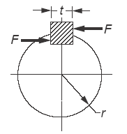
Figure 1 Shaft Keyway Dimensional
Preview Premium Access Only Shaft Keyway Shear and Yield Strength Required Calculator
Eq. 1
Keyways in Shaft or Hub
Ssy / n = F / t · l
Rearrange for shear strength
Eq. 2
Shaft or axle diameter required
Ssy = n · F / ( t · l )
Eq. 3
Keyways in Shaft or Hub
Sy / n = F / [ ( t · l ) / 2 ]
Rearrange for yield strength
Eq. 4
Keyways in Shaft or Hub
Sy = n · F / [ ( t · l ) / 2 ]
where
n = safety factor, %;
F = force applied, lb
Ssy = shear strength, lbs/in2 (psi);
Sy = yield strength, lbs/in2 (psi);
t = key / keyway width, in;
l = length of keyway, in ;
Effect of Keyways on Shaft Strength. Keyways cut into a shaft reduce its load carrying ability, particularly when impact loads or stress reversals are involved. To ensure an adequate factor of safety in the design of a shaft with standard keyway (width, one-quarter, and depth, one-eighth of shaft diameter), the former Code for Transmission Shafting tentatively recommended that shafts with keyways be designed on the basis of a solid circular shaft using not more than 75 percent of the working stress recommended for the solid shaft.
Source:
- Budynas, Richard G., and J. Keith Nisbett, Shigley's Mechanical Engineering Design, 8th ed., New York: McGraw-Hill, 2008.
- Marks Standard Handbook for Mechanical Engineers
- Machinerys Handbook, 30th Edition
Related:
- Standard Metric Keys Keyways for Metric Bores with One Key
- Keyway Cutter Hole Keyway Dimensional Data for MIlling Centers and Arbors - ANSI/ASME B94.19-1997
- Keyway Stresses for Non-metallic Gears and Shafts Formulas and Calculator
- Shaft (Arbor) Keyway Dimensional Data - ANSI/ASME B94.19-1997
- Design of Square Key and Keyway (Wood Ruff) Stress, Shear and Torque
- Metric Key Keyway Dimensions
- Parallel Key and Taper Keys Dimensions
- Shaft with Keyway Torque Applied Deformation and Stress Equations and Calculator
- Shaft with Two Keyways Torque Applied Deformation and Stress Equations and Calculator