Related Resources: calculators
Shear Center for Beams Equations and Calculator
Civil Engineering and Design
Strength of Materials Basics and Equations | Mechanics of Materials
Beam Deflection and Stress Calculators Formulas & Structural Analysis
Shear Center for Beams Equations and Calculator
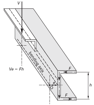
A beam with a symmetrical cross section supporting a transverse force that is offset from the longitudinal centroidal axis will be acted upon by a torsional moment, and the beam will tend to “roll” about a longitudinal axis known as the bending axis or torsional axis. For solid, symmetrical cross sections, this bending axis passes through the centroid of the cross section. However, for an asymmetrical beam (e.g., a channel beam on its side), the bending axis passes through the shear center (flexural center, torsional center, or center of twist), not the centroid. (See Fig. 1.) The shear center is a point that does not experience rotation (i.e., is a point about which all other points rotate) when the beam is in torsion.

Figure 1, Channel Beam in Pure Bending
(shear resultant, V, directed through shear center, O)
For beams with transverse loading, simple bending without torsion can only occur if the transverse load (shear resultant, V, or shear force of action) is directed through the shear center. Otherwise, a torsional moment calculated as the product of the shear resultant and the torsional eccentricity will cause the beam to twist. The torsional eccentricity is the distance between the line of action of the shear resultant and the shear center.
The shear center is always located on an axis of symmetry. The location of the shear center for any particular beam geometry is determined by setting the torsional moment equal to the shear resisting moment, as calculated from the total shear flow and the appropriate moment arm. In practice, however, shear centers for common shapes are located in tables similar to Fig. 2.
Preview Shear Centers of Selected Thin-Walled Open Sections Calculator
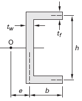
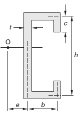
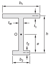
Shear Centers of Selected Thin-Walled Open Sections*
Simple Channel Shear Center Equation

Eq. 1
e = ( 3 · tf · b2 ) / ( h · tw + 6 · b · tf )
"C" Section Shear Center Equation
Open "C" Section Shear Center Calculator

Eq. 2
e = b [ ( 3 · h2 · b + 6 · h2 · c - 8 · c3 ) / ( h3 + 6 · h2 · b + 6 · h2 · c + 8 · c3 - 12 · h · c2 ) ]
Modified "I" Section Shear Center Equation
Modified "I" Section Shear Center Calculator

Eq. 3
e = ( t1 · b31 · h ) / ( t1 · b31 + t2 · b32 )
*Distance e from shear center, O, measured from the reference point shown. Distance e is not the torsional eccentricity, which is the separation of the shear center and the line of action of the shear force.
Reference
Civil Engineering Reference Manual, Fifteenth Edition, Michael R. Lindeburg, PE
Related
- Section Properties Area Moment of Inertia of Common Shapes
- Polar Moment of Inertia, Polar Section Modulus Properties of Common Shapes
- Structural Steel AISC Shapes Properties Viewer
- Mass Moment of Inertia Equations
- Moment of Inertia, Section Modulus, Radii of Gyration Equations Square and Rectagular Sections
- Moment of Inertia, Section Modulus, Radii of Gyration Equations Circular, Eccentric Shapes
- Moment of Inertia, Section Modulus, Radii of Gyration Equations Triangular, Hex Sections
- Slender Rod Moment of Inertia Calculator
- Moment of Inertia, Section Modulus, Radii of Gyration Equations I Sections
- Thin Wall Shaft Mass Moment of Inertia
- Calculator Moment of Inertia Equation, Section Modulus Equation, Radii of Gyration Equations Channel Sections
- Cylindrical Shaft Moment of Inertia Equations
- Trapezoid Section Properties Calculator