Related Resources: calculators
Stress at Threaded Tube Connection Design Calculator
Threaded Connections Design and Calculations
Strength of Materials
Stress at Threaded Connections Between Two Tubes Design and Calculator
The following rules are stated for the case of threaded connections between two tube subjected to axial force, P. For the bolt-and-nut assembly, the same rules apply, by substituting Di = O.
Preview calculator: Design Stress at Threaded Connections Between Two Tubes Calculator
Eq. 1 Tensile stress in outer tube at root section of thread
Eq. 2 Tensile stress in outer tube at relief groove
Eq. 3 Tensile stress in inner tube at root section of thread
Eq. 4 Tensile stress in inner tube at relief groove
Eq. 5 Shear stress across threads, along a cylindrical surface having a diameter equal to the minimum pitch diameter.
Eq. 5a
Eq. 5b
Eq. 5c Unloaded tooth
Utooth = Δo - ΔI
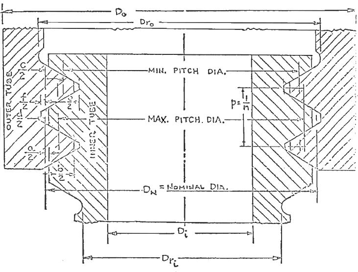
Figure 1 - Tube to Tube threaded Connection
Eq. 6 Bearing stress on the surface of contact between inner and outer threads.
Eq. 7 Hoop compression stress in inner tube
Eq. 7a The corresponding elastic decrease in diameter of the inner tube is
Eq. 8 Hoop tension stress in outer tube
Eq. 8a
Where
P =axial tensile force
DN = Nominal diameter
Do = Outer tube thread root diameter
Dro = Outer tube major diameter
Di = Inside tube inside diameter
Dri = Inside tube root diameter
L = Length of engagement
ΔI = elastic decrease in diameter of inner tube
ΔO = elastic increase in diameter of outer tube
a = Truncation of external thread root
b =
Total single thread contact width
p = pitch
c = Difference between maximum major and pitch diameter of internal thread
d = Height if internal thread and depth of thread engagement
e = Double height of external thread
f = Addendum of external thread
ft = Tensile stress
Utooth = Unloaded tooth height
Ltooth = Loaded tooth height
L = Length of engaged thread
Reference:
- Bell Helicopter Structural Design Manual, 1977
Unloaded Tooth Height
Related
- Screw Thread Size Chart
- Length of Screw Thread Engagement per. ISO 965-1 Calculator , Formula and Table Length of engagement of mating threads is selected to utilize full tensile strength of a bolt prior to shearing and nut threads.
- Bolt Fastener Tightening Methods Review
- Bolt Head or Nut Friction Torque Formula and Calculator per. MIL-HDBH-60
- Bolt Elongation Stress Formulas and Calculator per. MIL-HDBH-60 Micrometer Bolt Elongation Method: Below the proportional limit. bolt elongation is directly proportional to axial stress, i.e., elongation increases in the same proportion as stress increases.
- Bolt Fastener Preload Torsion Load Stress Formulas and Calculator per. MIL-HDBH-60
- Bolt Elongation by Turn Formulas and Calculator per. MIL-HDBH-60
- Bolt Torque on Assembly for Gasket Contact Stress per. ASME PCC-1 Equations and Calculator
- Torque Clamp Force Calculator
- Stud Preload Calculator
- Bolt Preload Tension Equation and Calculator
- Bolt Preload Tension Force Calculator
- Torque vs Tension Bolts Table Chart SAE J429 Bolts
- Bolt Multiple Diameters Change of Length Under Axial Force Formula and Calculator
