Related Resources: calculators
Structural Beams Diagrams Python Application Script
Beam Deflection and Stress Calculators Formulas & Structural Analysis
Beams diagrams for shear, moments, angle, and deflection Python Application Script
This applications is python-based to perform engineering analysis on beams with diagrams for shear, moments, angle, and deflection
Perform engineering analysis on beams with diagrams for shear, moments, angle, and deflection including 3D plots.
Python code - This application requires knowledge of Python installation and code execution.
NOTE:
Refunds are not awarded after Python files have been downloaded - review your membership agreement for details.
Units (if utilized) utilized within calculators are either SI or Imperial (some enable both SI and Imperial) and member (you) are responsible for conversions. Ensure that you verify units utilized in excel application meet your requirements before downloading.
Premium Membership Required for download
Download: Beams Diagrams for Shear, Moments, Angle, and Deflection
Sample Code
E = 207 * 10 ** 6
L = 1.0
CS = CrossSection ( CrossSectionTypes . CIRC , [ .01 ])
B = Beam ( L , E , crossSection = CS )
B . addPointLoad ( 0 , 11 , 45 )
B . addPointLoad ( L / 2 , - 20 , 45 )
B . addPointLoad ( L , 11 , 45 ) B . addDistributedLoad ( 0 , L , - 2 , 45 ) B . addBoundaryCondition ( L / 2 , BoundaryConditionTypes . ANGLE , 0 )
B . addBoundaryCondition ( L , BoundaryConditionTypes . DEFLECTION , 0 )
B . runAnalysis ( outputToFile = True )
Requirements
- Currently reactions are not solved for...
- All loads and reactions must be inputted
- Boundary conditions currently required
- one angle AND one deflection value
- OR two deflection parameters
- Beam weight is not accounted for by default
- represent it with a distributed load
Python Module Requirements
numpy
matplotlib
# Testing
pytest
Application demos
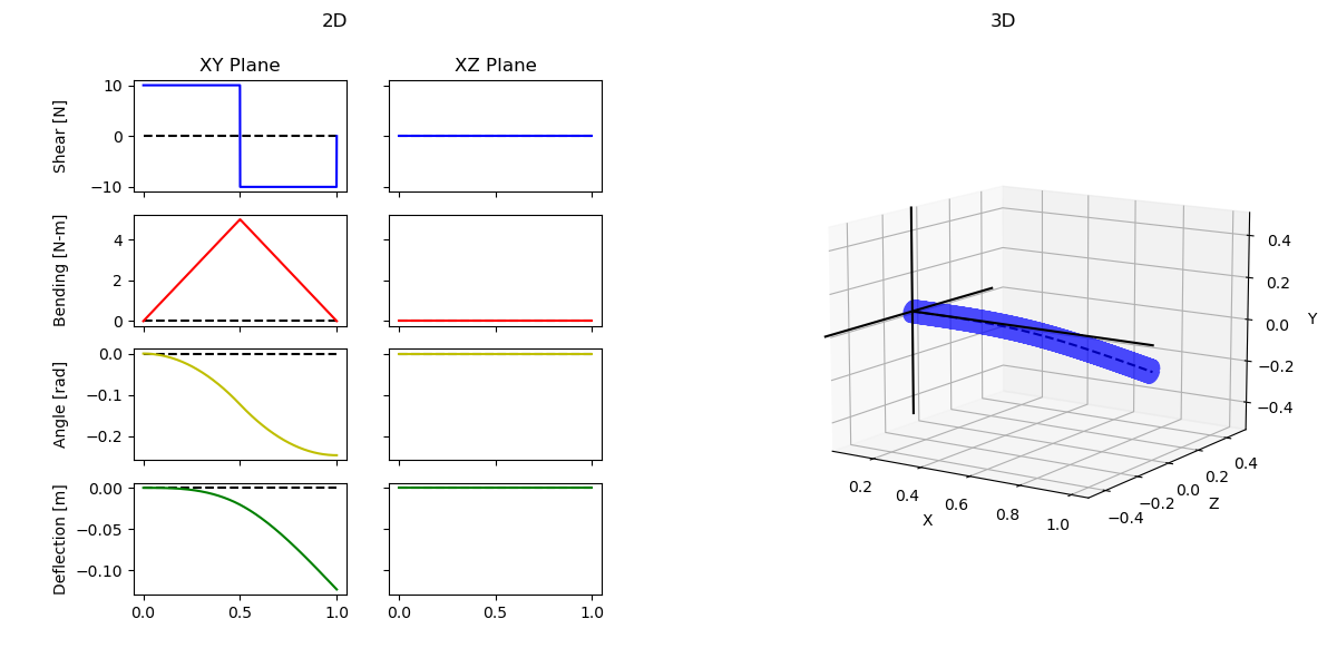
Simple Cantilever Beam
Cantilever Graphs
Cantilever Analysis Console Output
[BEAM ANALYSIS] - Running analysis with beam parameters:
[BEAM ANALYSIS] - length: 1.0
[BEAM ANALYSIS] - Young's modulus of material: 2070000
[BEAM ANALYSIS] - Moment of inertia: 4.9087385212340526e-06
# =============================================================================== #
[BEAM ANALYSIS] - [SOLVING] - Solved for xy angle constant C1 = 0.0
[BEAM ANALYSIS] - [SOLVING] - Solved for xy deflection constant C2 = 0.0
# =============================================================================== #
[BEAM ANALYSIS] - Singularity functions in XY:
10.0 - 20.0<x - 0.5>^0 + 10.0<x - 1.0>^0
10.0<x - 0>^1 - 20.0<x - 0.5>^1 + 10.0<x - 1.0>^1
(10.0 / 2)<x - 0>^2 - (20.0 / 2)<x - 0.5>^2 + (10.0 / 2)<x - 1.0>^2 + 0.0
(10.0 / 6)<x - 0>^3 - (20.0 / 6)<x - 0.5>^3 + (10.0 / 6)<x - 1.0>^3 + 0.0 + 0.0
# =============================================================================== #
[BEAM ANALYSIS] - Report in XY:
Max Shear: 10.0 [N]
Max Moment: 4.995 [N-m]
Max Angle: 0.24604 [rad]
Max Deflection: 0.12302 [m]
# =============================================================================== #
Cantilever Input Parameters and Loads
# =================================== #
# 1. Define Beam Parameters #
# =================================== #
# E - Youngs Modulus #
# I - Moment of Inertia I #
# L - Beam Length #
# =================================== #
E = 207 * 10**4
L = 1.0
CS = CrossSection(CrossSectionTypes.CIRC, [.05])
B = Beam(L, E, crossSection=CS)
# =================================== #
# 2. Add Loads #
# =================================== #
# Use theta = 0 to indicate XY plane #
# Use theta = 90 to indicate XZ plane #
# #
# | (90 - XZ plane) #
# \ | #
# \ | #
# \|________ (0 - XY plane) #
# =================================== #
B.addPointLoad(0, 10, 0)
B.addPointLoad(L/2, -20, 0)
B.addPointLoad(L, 10, 0)
# =================================== #
# 3. Input Boundary Conditions #
# =================================== #
# Use the loading angle convention #
# =================================== #
# B.addBoundaryCondition(L/2, BoundaryConditionTypes.ANGLE, 0)
B.addBoundaryCondition(0, BoundaryConditionTypes.DEFLECTION, 0)
B.addBoundaryCondition(0, BoundaryConditionTypes.ANGLE, 0.0)
# =================================== #
# 4. Run Analysis #
# =================================== #
B.runAnalysis()
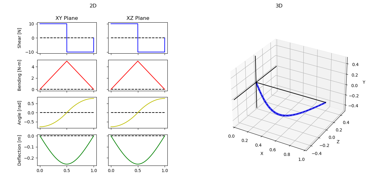
Fixed-Support Beam
Fixed-Support Graphs
Fixed-Support Analysis Console Output
[BEAM ANALYSIS] - Running analysis with beam parameters:
[BEAM ANALYSIS] - length: 1.0
[BEAM ANALYSIS] - Young's modulus of material: 207000000
[BEAM ANALYSIS] - Moment of inertia: 7.853981633974483e-09
# ================================================================================ #
[BEAM ANALYSIS] - [SOLVING] - Solved for xy angle constant C1 = -1.25
[BEAM ANALYSIS] - [SOLVING] - Solved for xy deflection constant C2 = 0.0
# ================================================================================ #
[BEAM ANALYSIS] - [SOLVING] - Solved for xz angle constant C1 = -1.25
[BEAM ANALYSIS] - [SOLVING] - Solved for xz deflection constant C2 = 0.0
# ================================================================================ #
[BEAM ANALYSIS] - Singularity functions in XY:
10.0 - 20.0<x - 0.5>^0 + 10.0<x - 1.0>^0
10.0<x - 0>^1 - 20.0<x - 0.5>^1 + 10.0<x - 1.0>^1
(10.0 / 2)<x - 0>^2 - (20.0 / 2)<x - 0.5>^2 + (10.0 / 2)<x - 1.0>^2 - 1.25
(10.0 / 6)<x - 0>^3 - (20.0 / 6)<x - 0.5>^3 + (10.0 / 6)<x - 1.0>^3 - 1.25 + 0.0
# ================================================================================ #
[BEAM ANALYSIS] - Singularity functions in XZ:
10.0 - 20.0<x - 0.5>^0 + 10.0<x - 1.0>^0
10.0<x - 0>^1 - 20.0<x - 0.5>^1 + 10.0<x - 1.0>^1
(10.0 / 2)<x - 0>^2 - (20.0 / 2)<x - 0.5>^2 + (10.0 / 2)<x - 1.0>^2 - 1.25
(10.0 / 6)<x - 0>^3 - (20.0 / 6)<x - 0.5>^3 + (10.0 / 6)<x - 1.0>^3 - 1.25 + 0.0
# ================================================================================ #
[BEAM ANALYSIS] - Report in XY:
Max Shear: 10.0 [N]
Max Moment: 4.995 [N-m]
Max Angle: 0.76886 [rad]
Max Deflection: 0.25629 [m]
# ================================================================================ #
[BEAM ANALYSIS] - Report in XZ:
Max Shear: 10.0 [N]
Max Moment: 4.995 [N-m]
Max Angle: 0.76886 [rad]
Max Deflection: 0.25629 [m]
# ================================================================================ #
Fixed-Support Input Parameters and Loads
# =================================== #
# 1. Define Beam Parameters #
# =================================== #
# E - Youngs Modulus #
# I - Moment of Inertia I #
# L - Beam Length #
# =================================== #
E = 207 * 10**6
L = 1.0
CS = CrossSection(CrossSectionTypes.CIRC, [.01])
B = Beam(L, E, crossSection=CS)
# =================================== #
# 2. Add Loads #
# =================================== #
# Use theta = 0 to indicate XY plane #
# Use theta = 90 to indicate XZ plane #
# #
# | (90 - XZ plane) #
# \ | #
# \ | #
# \|________ (0 - XY plane) #
# =================================== #
B.addPointLoad(0, 10, 0)
B.addPointLoad(0, 10, 90)
B.addPointLoad(L/2, -20, 0)
B.addPointLoad(L/2, -20, 90)
B.addPointLoad(L, 10, 0)
B.addPointLoad(L, 10, 90)
# =================================== #
# 3. Input Boundary Conditions #
# =================================== #
# Use the loading angle convention #
# =================================== #
# B.addBoundaryCondition(L/2, BoundaryConditionTypes.ANGLE, 0)
B.addBoundaryCondition(0, BoundaryConditionTypes.DEFLECTION, 0)
B.addBoundaryCondition(L, BoundaryConditionTypes.DEFLECTION, 0.0)
# =================================== #
# 4. Run Analysis #
# =================================== #
B.runAnalysis()
Source
Python code - This application requires knowledge of Python installation and code execution.
Support:
- Engineers Edge has tested the basic functions and operation of this application using Python 3.11.9 and supporting modules.
- Supporting Windows application "Visual Studio Code".
- THE SOFTWARE IS PROVIDED "AS IS", WITHOUT WARRANTY OF ANY KIND, EXPRESS OR IMPLIED, INCLUDING BUT NOT LIMITED TO THE WARRANTIES OF MERCHANTABILITY, FITNESS FOR A PARTICULAR PURPOSE AND NONINFRINGEMENT. IN NO EVENT SHALL THE AUTHORS OR COPYRIGHT HOLDERS BE LIABLE FOR ANY CLAIM, DAMAGES OR OTHER LIABILITY, WHETHER IN AN ACTION OF CONTRACT, TORT OR OTHERWISE, ARISING FROM, OUT OF OR IN CONNECTION WITH THE SOFTWARE OR THE USE OR OTHER DEALINGS IN THE SOFTWARE.
Related
- Beam Stress and Deflection Equation and Calculator Structural Beam Deflection, Stress, Equation and Calculator for a Beam with Ends Overhanging Supports and Two loads.
- Beam Stress & Deflection Equation and Calculator For Beam at Supported at Both Ends and Two equal Loads Beam Supported on Both Ends With Two Loads Applied at Equal Length From Structural Ends.
- Beam Stress and Deflection Equations and Calculator for Structural Beam Beam Supported on Both Ends With Overhanging Supports of equal Length and Equal Loads
- Beam Deflection Calculator Supported on Both Ends Uniform Loading Deflection and Stress Stress, Deflection Equation and Calculator using total applied load and line load.
- Beam Stress & Deflection Equations / Calculator Cantilevered Beam Structural Beam Deflection, Stress Equations and calculator for a Cantilevered Beam with Uniform Load.
- Beam Three Supports Uniform Load, Moments, Shear, Reactions and Deflections Equations and Calculator
- Beam Three Supports Concentrated Load between two supports , Moments, Shear and Reactions Equations and Calculator.
- Beam Four Supports with Three Concentrated Loads Applied Supports, Moments, Shear and Reactions Equations and Calculator
- Curved Beam Stress and Deflection Design Spreadsheet Calculator
- Beam Defection and Stress Free and Guided on One End, Rigid one End With Uniform Load
- Cantilevered Beam Deflection Calculator, Shear, Deflection and Stress Equations and calculator for a Beam supported One with Tapered Load
- Beam Distributed Load Deflection, Shear, Deflection and Stress Equations and Calculator
- Equations and Calculator Deflections and Stress for a Beam supported One End, Pin Opposite End and One Tapered Distributed Load
- Calculator for a Beam supported One End, Pin Opposite End and Single Moment at End Applied Deflection and Stress Calc
- Beam Stress Equations and Calculator for a Beam supported One End, Cantilevered Single Load at End
- Stress & Deflection Equations and Calculator for a Beam Supported One End, Cantilevered at Defined Location and Single Moment Applied at End
- Stress & Deflection Equations and Calculator for a Beam Supported One End, Cantilevered at Defined Location and Uniform loading Applied
- Beam Stress Deflection Calculator - Fixed at Both Ends, Load at any Location

