Related Resources: Design Engineering
AGMA Spur Gear Bending Stress Excel Spreadsheet Calculator
NOTE:
- Refunds are not awarded after excel files have been downloaded - review your membership agreement for details.
- This excel spreadsheet may contain macros which will need to be enabled in your excel application, see web page: Enable macros in Downloaded excel files
- Units utilized within calculators are either SI or Imperial (some enable both SI and Imperial) and member (you) are responsible for conversions. Ensure that you verify units utilized in excel application meet your requirements before downloading.
Electrical, Instrumentation, Electronic Design and Engineering
AGMA Spur Gear Bending Stress Equation and Spread Sheet (1999)
The AGMA* spur gear bending method can be viewed as a detailed refinement of the Lewis method.

Eqn. 14.58
Where:
Yj is the Lewis form factor corrected for several geometry factors, including stress concentration effects.Fig 14.30
Ka is the Application factor (1 to 2.75) that accounts for pulsation and shock in the driver and load. Table 14.8
Ks is the Size factor (1 to 1.4) which penalizes very large or wide teeth.
Km is the Load Distribution factor (1 to 2) that is a function of face width. paragraph 14.11.3
KV is the Dynamic factor (1 to 1.8), essentially a tailored Barth velocity factor that considers gear quality. Fig. 14.34
Ki is the Idler factor (1 or 1.42), accounting for reversed bending in idlers.
KB is the Rim Thickness factor which penalizes for the rim flexibility of non-solid gears. Eqn. 14.67
* American Gear Manufacturers Association, all units given in Imperial Units.
Note: Accessing this resource requires an active Premium Membership with Engineers Edge
Download: AGMA Spur Gear Bending Stress Equation and Spread Sheet
Preview: AGMA Spur Gear Bending Stress Equation and Spread Sheet
This excel document contains macros which will need to be enabled in your excel application.
Instructions
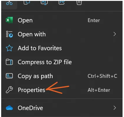
Go to the file location of the Excel file.
Right-click and select Properties.

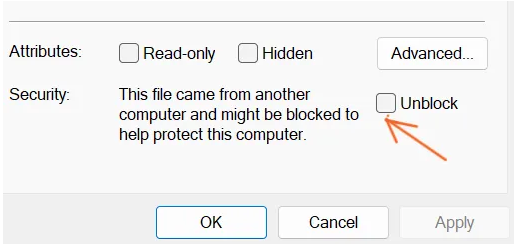
Select the Unblock checkbox at the bottom of the General tab in Properties, then select OK .

Related:
- AGMA Gear Tooth Bending Stress Formula and Calculator Per standard ANSI/AGMA D04 Fundamental Rating Factors and Calculation Methods for Involute Spur and Helical Gear Teeth:
- AGMA Major metallurgical factors affecting the allowable contact stress number , s ac , and allowable bending stress number
- Gear Design Handbook Premium Membership Required
- AGMA Spur Gear Profile Calculator Spread Sheet - Three excel calculation sheets that include the following input data/variables, calculated data and chart graphics.
- AGMA Worm and Spur Gear Design Equations and Calculators Worm gear sets are generally rated by their capacity to handle a particular level of input power, output power, or allowable torque at a particular speed for the input or output shaft.
- AGMA Worm gear Equations For Rating Factors Values for the ratio correction factor, the velocity factor, and materials factors can be found from tables provided in the ANSI/AGMA 6034-B92 standard.
- Practical Gear Design and Manufacture Handbook 872 pages, Premium account required, Gears are produced in enormous amounts - billions of gears are produced by industries every year. While the automotive industry ranks as the primary consumer of gears, numerous other industries also require huge amounts of gears: aerospace (helicopter transmission, etc. ), construction machinery, and agricultural machinery, to name a few.
- AGMA Fine Pitch Tolerances for Gears Gear tolerance chart below, lists the more common tolerance or quality specifications assigned for Spur, Helical and Herringbone type gears.
- AGMA Spur Gear Bending Stress Equation and Spread Sheet (1999) The AGMA* spur gear bending method can be viewed as a detailed refinement of the Lewis method.
- Analytical Mechanics Of Gears The subtitle of this treatise could well be Final Report of the ASME Special Research Committees on Worm Gears and the Strength of Gears