Related Resources: fluid flow
O-Ring Leak Rate Equation and Calculator
Engineering Fluids | O-Ring Design DataLeak rate of a gas through an O-ring seal can be approximated when the permeability of the gas through the particular o-ring elastomer is known for the temperature at which the o-ring seal must operate. The following equation is used to determine the approximation:
L = 0.7 F D P Q (1-S)2
Where:
L = Approximate leak rate of the seal, std. cc/sec.
F = Permeability rate of the gas through the o-ring elastomer at the expected operating temperature, (std. cc cm/cm2 sec bar) x 10-8
D = contact length of the O-ring, inches (rectangular or square type).
P = Pressure differential across the o-ring seal, lb/in2
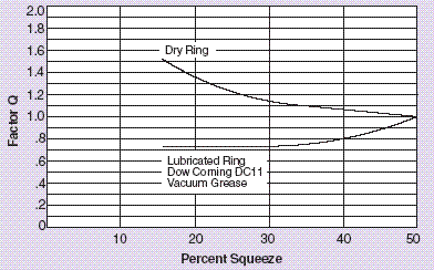
Q = Factor based on the percent squeeze and whether the O-ring is lubricated or dry.
S = Percent squeeze on the O-ring cross section expressed as a decimal. (i.e., for a 20% squeeze, S = .20)
This calculator requires a Premium Membership
This equation provides a rough order of magnitude and approximation because permeability varies between compounds in the same o-ring polymer, and because the assumptions on which it is based are not all exact.
These assumptions are:
1. The cross section of a squeezed O-ring is rectangular or square.
2. The cross section area of a squeezed O-ring is the same as its area in the free condition.
3. The permeability rate of a gas through an O-ring is proportional to the pressure differential across the seal.
NOTE: For convenience, the formula contains mixed units. It was set up this way because in the United States O-ring diameters are usually given in inches, and pressures in pounds per square inch while permeability figures are usually shown in metric units. The 0.7 factor/constant resolves these inconsistencies.

Q-Rate
For helium leak rate, a variation of ±50% of the predicted value should be anticipated to allow for limitations in the accuracy of test equipment and available standards, and for variations between samples.
Related:
- O-Ring Installation Design and Specification Static Cylindrical Installations
- O-Ring Installation Design and Specification Static Flange Application
- O-Ring Installation Design and Specification For Dynamic Applications
- O-Rings Design Guidelines, Specifications, Materials
- O-Ring Installation Compressive Load vs Hardness Chart .070 Diameter O-Ring Table
- O-Ring Installation Compressive Load vs Hardness Chart .210 Diameter O-Ring
- O-Ring Installation Compressive Load vs Hardness Chart .275 Diameter O-Ring
- O-Ring Installation Compressive Load vs Hardness Table Chart .139 Diameter O-Ring
- O-Ring Installation Compressive Load vs Hardness Chart .103 Diameter O-Ring
- Groove Design for Metric ISO Size O-Rings per. ISO 3601-2
- Poppet Seal Gasket O-ring Operating Life and Reliability Equations and Calculator
- Analysis of Large-Sized O-Rings