Related Resources: gears
AGMA Allowable Contact Stress for Steel Gears Table
AGMA Allowable Contact Stress, sac, for Steel Gears Table
The allowable stress numbers for gear materials vary with items such as material composition, cleanliness, residual stress, microstructure, quality, heat treatment, and processing practices. For materials other than steel, a range is shown, and the lower values should be used for general design purposes.
Allowable stress numbers shown in the table below are determined or estimated from laboratory tests and accumulated field experiences. They are based on unity overload factor, 10 million stress cycles, unidirectional loading and 99 percent reliability.
The grade cleanliness requirements apply only to those portions of the gear material where the teeth will be located, to a distance below the finished tip diameter of at least two times the tooth depth. On external gears this portion of the gear blank normally will be less than 25 percent of the radius.
| Material | Heat treatment |
Min. Surface Hardness1 |
sac Allowable contact stress number2 lb/in2 |
||
Grade 1 |
Grade 2 |
Grade 3 |
|||
| Steel3 |
Through hardened4 |
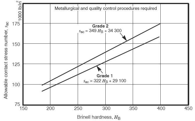
see figure 1 |
see figure 1 |
see figure 1 |
---- |
Flame5 or induction hardened5 |
50 HRC |
170,000 |
190,000 |
---- |
|
54 HRC |
175 000 |
195 000 |
---- |
||
Carburized and hardened5 |
see table 9 |
180 000 |
225 000 |
275 000 |
|
Nitrided5 ( through hardened steels) |
83.5 HR15N |
150 000 |
163 000 |
175 000 |
|
84.5 HR15N |
155 000 |
168 000 |
180 000 |
||
| 2.5% Chrome (no aluminum) |
Nitrided5 |
87.5 HR15N |
155 000 |
172 000 |
189 000 |
| Nitralloy 135M |
Nitrided5 |
90.0 HR15N |
170 000 |
183 000 |
195 000 |
| Nitralloy N |
Nitrided5 |
90.0 HR15N |
172 000 |
188 000 |
205 000 |
| 2.5% Chrome (no aluminum) |
Nitrided5 |
90.0 HR15N |
176 000 |
196 000 |
216,000 |
Notes:
1 Hardness to be equivalent to that at the start of active profile in the center of the face width.
2 See tables 7 through 10 of the standard AGMA/ANSI -D04 for major metallurgical factors for each stress grade of steel gears.
3 The steel selected must be compatible with the heat treatment process selected and hardness required.
4 These materials must be annealed or normalized as a minimum.
5 The allowable stress numbers indicated may be used with the case depths.
Click on image to enlarge

Figure 1 Allowable contact stress number for through hardened steel gears, sac
Related
- Strength of Materials Basics and Equations | Mechanics of Materials
- Stress Equation Defintion - Strength Mechanics of Materials
- Stress Equation Defintion - Strength ( Mechanics ) of Materials
- Analysis of Stress and Deformation
- Plastic Spur Gearing Design Hp and Operating Stress Equations and Calculator
- Plastic Straight Bevel Gears Rated Design Hp, Operating Stress Equations and Calculator
- Spur Gear and Assembly Builder Spur Gear and Assembly Builder calculates and models individual Spur Gears and Gear assembly. File down loads available with Premium Account.
- Spur Gear Generator with Download Spur Gear Generator is unitless: you may choose inches, cm or millimeters when importing your DXF file as you will have the same value for D/P as it is set above or as imported (SI or imperial units).
Source:
- ANSI/AGMA American National Standards Institutue. American Gear Manufacturers Association Specification AGMA 201-D04