Related Resources: gears
Force Analysis Spur Gears Equation and Calculator
Gear Design and Engineering
Machine Design and Application
Force Analysis for Spur Gears Equation and Calculator
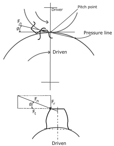
Power and torque is transmitted when a tooth of an input gears exerts a force Fn along the pressure line on the tooth of output gear - See Figure A:

Figure A
The force Fn resolves into two components, the tangential Ft , the radial component Fr , which are related to the pressure angle as:
Ft = Fn · cos Φ
Fr = Fn · sin Φ
Fr = Ft · tan Φ
Torque and Power Transmission:
The torque ( Mt ) in N-mm and power in kW transmitted by gear are:
Mt = Ft · r
kW = 2 Π n Mt / ( 60 x 106 )
Where, n is the rotational speed of the gear in rpm; and r is the radius of the pitch circle.

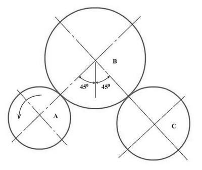
Figure B
Spur Gear System with Idler or a Carrier Gear

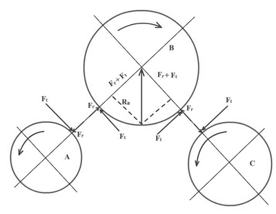
Figure C
Free Body Diagram Spur Gear System
Gear B is an idler and it transmits torque it receives from gear A and the gear C. The tangential component of force between gears A, B and C must equal to the tangential component of force between gears A and B.
Therefore, the two radial components of forces acting on the gear B are equal as Fr = Ft tanφ. The reaction force RB on the idler gear shaft is given by:
RB = [ ( Fr + Ft)2 + ( Fr + Ft)2 ]1/2 = [ 2 ( Fr + Ft)2]1/2
RB = (2)1/2 ( Fr + Ft ) = (2)1/2 = (2)1/2 Ft ( 1 + tan Φ )
Assuming pressure angle 20°
RB = (2)1/2 Ft ( 1 + 0.364 )
If the weight of the idler gear ( W ) is equal to RB , then W = 1.93 Ft .
If the idler is located at the bottom, the reaction force will still act upwards but will be less, since the components of reaction force would be - Fr + Ft. This gives you RB = Ft. Therefore, it is recommended that the idler gear be placed over the input and output gears.
Should the design be that the input and output gears revolve in a clockwise direction, both the reaction and weight of the idler acts downward. Is this case the preferred location of the idler would be on the top side, if the idler is mounted on a moveable arm and not on a rigid mounted shaft.
Where:
W = Weight (N)
P = Load / Force (N)
Rb, A, B = Reaction Load / Force (N)
φ = Angle (deg.)
r = radius pitch circle (mm)
n = rpm
Reference: Machine Elements and Drives, NPTEL