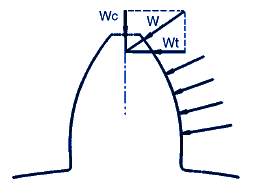
Gear Tooth Strength Calculation and Equation
Gear Products and Suppliers | Gear Knowledge Menu
The following is general guidelines for determining or estimating your required gear tooth strength.
Wilfred Lewis, in 1892, presented his expression for tooth beam strength which is now reknowned as the classic Lewis equation. As a static beam resisting a fixed load in position and magnitude, this equation is usually adequate. However, it does not take into account the dynamics of meshing teeth. In that regard, later investigators have modified and improved the original Lewis equation.
When a gear train system is transmitting power and motion, it is safe to assume that all of the load is being carried by one tooth.This is most correct because as the load approaches the end of the tooth, where the bending force would be the greatest, a second tooth comes into mesh to share the load. Simple results can be obtained from the Lewis bending strength equation.
Eq. 1
Wt = ( S · F · Y ) / Dp
Eq. 2
DP = t / pd
Where:
W = Maximum transmitted load (lbs, N)
S = Maximum bending tooth stress taken as 1/3 of the tensile strength (psi, N/mm2)
F = Face width of gear (in, mm)
DP
= Diametral Pitch, (in, mm).
Y = Lewis Factor (See Lewis Factor for Gears) (no units)
t = number of teeth, #
pd = pitch circle of gear teeth (in, mm)
The conversion formula for the module (m) from the diametral pitch (DP) is as follows:
m = 25.4 /DP
The Lewis factor is dimensionless and independent of tooth size, and a function only of shape.
Open Gear Tooth Strength Calculator

The maximum bending tooth stress (S) is valid for well lubricated, low shock applications. For high shock, poorly lubricated applications, the safe stress could be as low as .025S. If your design calls for an harsh environment for your gear application, you might want to lower S to assure a reasonable amount of gear life.
Reference
1. Earle Buckingham, Manual of Gear Design",3 Vols., Industrial Press, New York, 1935
2. Chironis, N.P.(Editor): "Gear Design and Application", McGraw-Hill Book Co., Inc. New York, NY., 1967
3. D.W. Dudley, "Gear Handbook", McGraw-Hill, NewYork,1962
4. Knut 0. Kverneland (Editor), "World Metric Standards for Engineering", Industrial Press, New York, NY. 1978
5. G.W. Michalec,"Precision Gearing: Theory and Practice", John Wiley & Sons, New York, 1966
6. J.E. Shigley,"Mechanical Engineering Design", McGraw-Hill, New York, 1963
7. W. Steeds,"Involute Gears, Longmans, Green and Co., London, 1948
8. El. DuPont de Nemeurs and Co., "Gears of DELRIN and ZYTEL’", Wilmington, Delaware.
9. Celanese Plastics and Specialties Co., "Design and Production of Gears in CELCON Acetal Copolymer", Chatham, New Jersey,
1979
10. The Polymer Corp, "Nylatron Nylon Gear Design Manual’, Reading, Pa.
11. L.D. Martin, "Injection Molded Plastic Gears",
Plastic Design and Processing Magazine , Pt.1 ,pp. 38-45. August 1968.
12. E.l. DuPont de Nemours and Co.. DELRIN Design Handbook", Willinggton. Delaware, 1967
13. Clifford E. Adams, "Plastie Gearing" Marcel Dekker, Inc. New YorK 1986 -
Related:
- AGMA Contact Stress Number Formula for Gear Tooth Equation and Calculator Per standard ANSI/AGMA D04 Fundamental Rating Factors and Calculation Methods for Involute Spur and Helical Gear Teeth:
- AGMA Gear Tooth Bending Stress Formula and Calculator Per standard ANSI/AGMA D04 Fundamental Rating Factors and Calculation Methods for Involute Spur and Helical Gear Teeth:
- Gear and Tooth Component Illustration A gear or cogwheel is a rotating machine part having cut teeth, or cogs, which mesh with another toothed part in order to transmit torque.
- Gear Equations, Calculators and Formula Spur Gear design formula for geometry, pitch, tooth clearance and critical functional data.
- Gear Terminology and Definitions Backlash is the amount by which the width of a tooth space exceeds the thickness of the engaging tooth on the pitch circles.
- Hertz Gear Tooth Contact Stress Equation and Calculator The transfer of power between gears takes place at the contact between the acting teeth. The stresses at the contact point can be computed by means of the theory of Hertz.
- Lewis Factor Equation Lewis factor Equation is derived by treating the tooth as a simple cantilever and with tooth contact occurring at the tip as shown above.