Related Resources: gears
Involute Spline and Serration Universal Design Calculator
Involute Spline and Serration Design Calculator for the following engineering standards:
-
ANSI B92.1-1970
- ANSI B92.1-1996
- ASA B5.15-1960
- SAE STANDARD - 1950
- SAE J500
- NAS 541/2, 580/1
- DS360/361
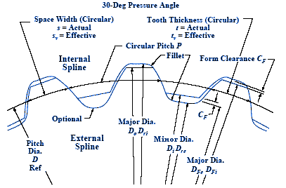
Preview Involute Spline and Serration Design Calculator per. ANSI B92.1

Where:
N = Number of Splines
DP = Diametral Pitch
PA = Pressure Angle
PD = Pitch Diameter
Calculator operational inputs notes.
ANSI, ASA, & SAE 1950:
Step 1: Enter only 1 thru 4 in the first box, the second box (DS dash #) should be left blank.
Step 2: Enter 1 or 2.
Step 3: Enter 1 thru 4 in the first box for the fit type. The second box applies only for
SAE 1950, and only for a major or minor fit type, otherwise leave it blank.
Step 4: Enter 1 or 2 for ASA, 4 thru 7 for ANSI, or 8 thru 10 for SAE 1950.
Step 5: Enter in the appropriate box the desired number of teeth, diametral pitch and
pressure angle. Leave the box for nominal diameter blank, it applies only for J500.
SAE J500
Step 1: Enter 5 in the first box, the second box (DS dash #) should be left blank.
Step 2: Enter 1 or 2.
Step 3: N/A, leave blank.
Step 4: N/A, leave blank.
Step 5: The ONLY required box to enter is the nominal diameter. It may be entered as a
decimal or a fraction. A space must be left between whole numbers and fractions.
Example: 1 (space bar) 3/4. Otherwise it will be read as 13/4 (Thirteen fourths).
NAS
Step 1: Enter 6 in the first box, the second box (DS dash #) should be left blank.
Step 2: Enter 1 or 2.
Step 3: N/A, leave blank. (all NAS have a fillet root)
Step 4: N/A, leave blank.
Step 5: Enter in the appropriate box the desired number of teeth, diametral pitch and
pressure angle. Leave the box for nominal diameter blank, it applies only for J500.
DS
Step 1: Enter 7 in the first box, enter the dash number in the second. Dash numbers
range from 306 thru 406 for DS360(EXT), and from 06 thru 106 for DS361(INT).
Step 2: Enter 1 or 2.
Steps 3 thru 5: N/A, leave blank. (N, DP, and PA are determined by the dash #)
Source:
Industry standards
ANSI B92.1, ASA B5.15, SAE Standard - 1950, SAE J500, NAS 541/2 ans NAS 580/1, DS 360/361
Related
- Involute Spline Engineering Drawing Data When defining engineering design data on an engineering drawing for involute splines, uniform and consistent specifications.
- Involute Spline per ANSI B92.1 Equations These splines or multiple keys are similar in form to internal and external involute gears.
- SAE Parallel Side Splines Table of Sizes and Dimensions
- Torque Applied Deformation and Stress of a Shaft with Two Splines Equations and Calculator
- Torque Applied Deformation and Stress of a Shaft with Four Splines Equations and Calculator
- Spline Engineering Design Formula ISO 5480standard applies to splined connections with involute splines based on reference diameters for connecting hubs and shafts..
- Classification and Accuracy Tolerances for Coarse-Pitch Spur and Helical Master Gears An inspection master gear is used with selected fixtures to measure the variations in a manufactured gear.
- Spur Gear Generator with Download Spur Gear Generator is unitless: you may choose inches, cm or millimeters when importing your DXF file as you will have the same value for D/P as it is set above or as imported (SI or imperial units).
- Spur Gear and Assembly Builder Spur Gear and Assembly Builder calculates and models individual Spur Gears and Gear assembly. File down loads available with Premium Account.
- AGMA Allowable Contact Stress, s ac , for Steel Gears Table The allowable stress numbers for gear materials vary with items such as material composition, cleanliness, residual stress, microstructure, quality, heat treatment, and processing practices. For materials other than steel, a range is shown, and the lower values should be used for general design purposes.
- AGMA Contact Stress Number Formula for Gear Tooth Equation and Calculator Per standard ANSI/AGMA D04 Fundamental Rating Factors and Calculation Methods for Involute Spur and Helical Gear Teeth:
- AGMA Gear Tooth Bending Stress Formula and Calculator Per standard ANSI/AGMA D04 Fundamental Rating Factors and Calculation Methods for Involute Spur and Helical Gear Teeth:
- AGMA Major metallurgical factors affecting the allowable contact stress number , s ac , and allowable bending stress number