Related Resources: gears
Planetary Epicyclic Gear Ratios Equations and Calculators
Equation and Calculators to determine Ratios of Planetary or Epicyclic Gear Assemblies
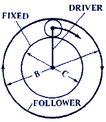
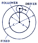
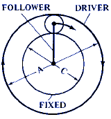
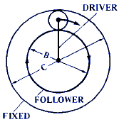
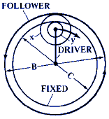
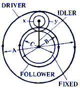
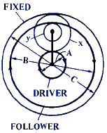
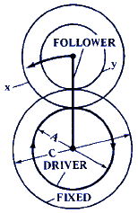
Where:
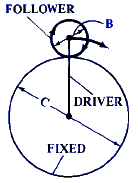
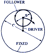
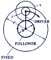
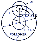
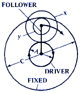
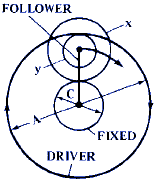
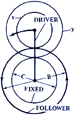
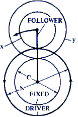
D = Rotation of driver per revolution of follower or the driven gear or Pulley. Revolution / Revolution ... or Speed Ratio Multiplier of the Driver to the Follower..
F = Rotation of follower or driven gear or pulley per revolution of driver. Note a (F = rotation of planet type follower about its axis.) or Speed Ratio Multiplier of the Follower to the Driver..
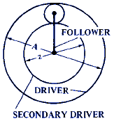
A = Size of driving gear use either number of teeth or pitch diameter. Note: When follower derives its motion both from A and from a secondary driving member, A = size of initial driving gear, and formula gives speed relationship between A and follower.
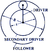
B = Size of driven gear or follower use either pitch diameter (inches or mm) or total number of teeth)
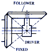
C = Size of fixed gear (use either pitch diameter or number of teeth)
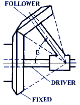
E = Angle in degrees
x = Size of planet gear as shown by diagram (use either pitch diameter or number of teeth)
y = Size of planet gear as shown by diagram (use either pitch diameter or number of teeth)
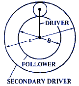
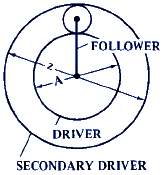
z = Size of secondary or auxiliary driving gear, when follower derives its motion from two driving members
S = Rotation of secondary driver, per revolution of initial driver. S is negative when secondary and initial drivers rotate in opposite directions. (Formulas in which S is used, give speed relationship between follower and the initial driver.)
RPM = Revolutions per Minute.
All Calculators require a Premium Membership
|
Illustration
|
Equation and Calculator for Gear Ratio
|
|---|---|
|
Figure 1 |
F = 1 + C / B Gear Ratio RPM Calculator Case 1
|
|
Figure 2 |
F = 1 - C / B |
|
Figure 3 |
F = C / B |
|
Figure 4 |
F = cos E + C / B |
|
Figure 5 |
F = 1 + ( x · C ) / ( y · B ) |
|
Figure 6 |
F = 1 + ( y · C ) / ( x · B) |
|
Figure 7 |
D = 1 + ( x · C ) / ( y ·A) |
|
Figure 8 |
D = 1 + ( y · C) / ( x · A ) |
|
Figure 9 |
F = 1 + C / B |
|
Figure 10 |
D = 1 + C / A |
|
Figure 11 |
D = 1 + C / A |
|
Figure 12 |
F = 1 + C / B |
|
Figure 13 |
F = 1 - [ ( C · x ) / ( y · B ) ] |
|
Figure 14 |
D = [ 1 + ( C / A) ] / { 1 - [ ( C · x ) / ( y · B ) ] } |
|
Figure 15 |
D = [ 1 + ( C / A) ] / { 1 - [ C · y ) / ( x · B ) ] } |
|
Figure 16 |
D = 1 - [ ( C · x ) / ( y · A ) ] |
|
Figure 17 |
F = 1 - [ ( C · x ) / ( y · B ) ] |
|
Figure 18 |
D = 1 - [ ( C · x ) / ( y · A ) ] |
|
Figure 19 |
F = 1 + [ z · ( 1 - S ) ] / B |
|
Figure 20 |
D = ( A + z ) / [ A + ( A · z ) ] |
|
Figure 21 |
D = ( A + z ) / [ A + ( S · z ) ] |
|
Figure 22 |
F = 1 + [ z · ( 1 - S ) ] / B |
|
Figure 23 |
D = 1 + C / A |
|
Figure 24 |
D = [ 1 + ( C / A ) ] / [ 1 - [ ( C · y ) / ( x · B ) ] |
Note: In all cases, if D is known, F = 1 / D, or, if F is known, D = 1 / F.
Direction of Rotation. Iif the calculated result is negative, the driver and follower will rotate in opposite directions; otherwise, a non-negative answer means tha both will rotate in the same direction.
Figures 19 - 22 are used to obtain the speed ratios when there are two driving members rotating at different speeds. These are Compound Drive types.
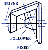
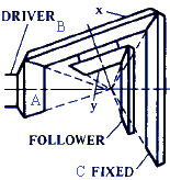
Planetary Bevel Gears.—Two forms of planetary gears of the bevel type are shown in Figures 23 and 24. The planet gear in Figure 23 rotates about a fixed bevel gear at the center of which is the driven shaft. Figure 24 illustrates the Humpage reduction gear. This is sometimes referred to as cone-pulley back-gearing because of its use within the cone pulleys of certain types of machine tools.
