Related Resources: hardware
Locking Mechanisms for Jig Bushings per. ANSI B94.33
Engineering ANSI Hardware Design Data
Engineering Metric Hardware Design Data
Manufacturing Technology and Design
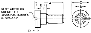
All dimensions in inches

Lock Screw for Slip and Fixed Bushings per. ANSI B94.33
No. |
A |
B |
C |
D |
E |
F |
UNC Thread |
LS-0 |
0.438 |
0.188 |
0.312 |
Per Manufacturer's Standard |
0.188 |
0.105-0.100 |
8–32 |
LS-1 |
0.625 |
0.375 |
0.625 |
0.250 |
0.138-0.132 |
5⁄16–18 |
|
LS-2 |
0.875 |
0.375 |
0.625 |
0.375 |
0.200-0.194 |
5⁄16–18 |
|
LS-3 |
1.000 |
0.438 |
0.750 |
0.375 |
0.200-0.194 |
3⁄8–16 |
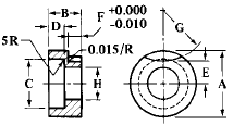
Round Clamp Option for Use with Reweable Bushing per. ANSI B94.33

Note: F dimension allows for clamping. Material and hardness specified by manufacturers standards. To change to the round clamo in old fixtures, remove the conventional screw and use the same tapped hole and use the new clamp with standard socket head screw.
Number |
A |
B |
C |
D |
E |
F |
G |
H |
Use With Socket Head Screw |
RC-1 |
0.625 |
0.312 |
0.484 |
0.150 |
0.203 |
0.125 |
0.531 |
0.328 |
5⁄16–18 |
RC-2 |
0.625 |
0.438 |
0.484 |
0.219 |
0.187 |
0.188 |
0.906 |
0.328 |
5⁄16–18 |
RC-3 |
0.750 |
0.500 |
0.578 |
0.281 |
0.219 |
0.188 |
1.406 |
0.391 |
3⁄8–16 |
Locking Mechanism Dimensions of Slip and Fixed Renewable Bushings per. ANSI B94.33

Body OD |
Max Diam. F When Used With Locking Device |
G Head Thickness |
H ± 0.005 |
J |
L Max |
R |
Locking Dim. of Lock Screw (Slip or Fixed) |
Locking Dim. of Clamp (Fixed Only) |
Max Head Diam. of Mating Liner Used to Clear Locking Device |
Clamp or Screw LS or RC |
|||||||||||
Slip |
Fixed |
||||||||||||||||||||
0.188 |
0.312 |
0.188 |
0.188 |
0.094 |
0.094 |
55° |
0.266 |
0.105-0.100 |
… |
… |
0 |
||||||||||
0.312 |
0.562 |
0.375 |
0.250 |
0.125 |
0.172 |
65° |
0.500 |
0.138-0.132 |
0.125-0.115 |
0.625 |
1 |
||||||||||
0.500 |
0.812 |
0.438 |
0.250 |
0.125 |
0.297 |
65° |
0.625 |
0.138-0.132 |
0.125-0.115 |
0.875 |
1 |
||||||||||
0.750 |
1.062 |
0.438 |
0.250 |
0.125 |
0.422 |
50° |
0.750 |
0.138-0.132 |
0.125-0.115 |
1.125 |
1 |
||||||||||
1.000 |
1.438 |
0.438 |
0.375 |
0.188 |
0.594 |
35° |
0.922 |
0.200-0.194 |
0.187-0.177 |
1.500 |
2 |
||||||||||
1.375 |
1.812 |
0.438 |
0.375 |
0.188 |
0.781 |
30° |
1.109 |
0.200-0.194 |
0.187-0.177 |
1.875 |
2 |
||||||||||
1.750 |
2.312 |
0.625 |
0.375 |
0.188 |
1.000 |
30° |
1.391 |
0.200-0.194 |
0.187-0.177 |
2.375 |
3 |
||||||||||
2.250 |
2.812 |
0.625 |
0.375 |
0.188 |
1.250 |
25° |
1.641 |
0.200-0.194 |
0.187-0.177 |
2.875 |
3 |
||||||||||
Jig Bushing Definitions: Renewable Bushings: Renewable wearing bushings to guide the tool are for use in liners which in turn are installed in the jig. They are used where the bushing will wear out or become obsolete before the jig or where several bushings are to be interchangeable in one hole. Renewable wearing bushings are divided into two classes, “Fixed” and “Slip.” Fixed renewable bushings are installed in the liner with the intention of leaving them in place until worn out. Slip renewable bushings are interchangeable in a given size of liner and, to facilitate removal, they are usually made with a knurled head. They are most frequently used where two or more operations requiring different inside diameters are performed in a single jig, such as where drilling is followed by reaming, tapping, spot facing, counterboring, or some other secondary operation.
Press Fit Bushings: Press fit wearing bushings to guide the tool are for installation directly in the jig without the use of a liner and are employed principally where the bushings are used for short production runs and will not require replacement. They are intended also for short center distances.
Liner Bushings: Liner bushings are provided with and without heads and are permanently installed in a jig to receive the renewable wearing bushings. They are sometimes called master bushings.