Related Resources: hardware
U-Bolt Application and Design
Common u-bolt installation and applications include the following:
- Antenna Section secured
- Wire cable
- Automotive Leaf Spring
- PIping supports
Applicable ASTM Specifications:
- A153 - Hot dip galvanizing specification.
- A193 - Alloy steel and stainless steel bolting materials for high temperature service.
- A194 - Carbon and alloy nuts for bolts for high pressure and high temperature service.
- A307 - Carbon steel bolts and studs ranging from 1/4" through 4" diameter.
- A320 - Alloy steel and stainless steel bolting materials for low temperature service.
- A325 - Structural bolts, steel, heat treated, 120/105 ksi minimum tensile strength.
- A354 - Quenched and tempered alloy bolts, studs, and other externally threaded fasteners.
- A449 - Quenched and tempered steel bolts and studs.
- A490 - Structural bolts, alloy steel, heat treated, 150 ksi tensile strength.
- A563 - Standard specification for carbon and alloy steel nuts.
- F1554 - Anchor bolts designed to anchor structural supports to concrete foundations.
- F2329 - New specification covering hot dip galvanizing.
|
|
|
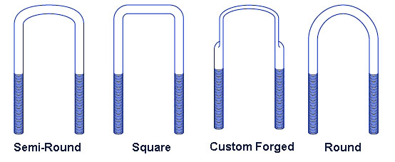
U-Bolt Types |
General U-bolt design Consideration:
Bend Radius
Round formed u-bolts, square or rectangular formed U or v-bolt the minimum bend radius is the driving design limitation The minimum ben radius achievable is governed by material characteristics, size and end-item strength requirements. During the bending or forming operation, deformation occurs at the radii as the material is stretched and compressed over the forming mandrel or tooling. During the forming operation, the material is yielded and plastic deformation in the form of diameter loss or necking at the bend area.
In general, the larger the radii per unit of material thickness, the less the necking or deformation of the material at the bend area. In general, one should design their u-bolt with the largest possible bend radius. The minimum radius should not be less than 1/2 X (0.5 X) the wire or rod diameter for low tensile materials and 11/16 (.69 X) the wire diameter for high tensile materials.
Steels with low toughness and ductility should have the radii larger than 11/16 X (.69 X) round diameter. Radii less than these are manufacture-able, however do tend to have excessive residual stresses in the bend area and cracking, excessive necking may occur during forming.
Be aware that a reduction in initial rod or wire diameter will occur in the bending area regardless of material characteristics.
Thread and Bend radius:
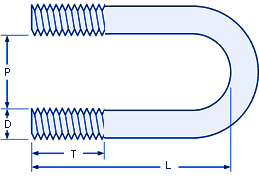
In general, thread are manufactured on the round stick before forming operations. The minimum distance between the last thread and the bend radius is not less than 1.5 X diameter of the round stock, however 2 X the u-bolt diameter is preferred.
Bend radius Flattening:
U-bolt Saddles, Saddle Clamp Plates:
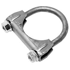
Saddle clamps are design or supplied and a matched set to the u-bolt. Saddle clamps are used to apply the clamping forces, distribute the assembly loading and properly secure to piping, antenna, etc. In the mage shown, the saddle clamp in manufactured by forming operations from flat sheet metal stock. The thru hole features where likely punched or pierced prior to the forming operations.
|
|
|
U-Bolt with Saddle Clamp |
 |
|||
|
Size
|
Thread Length
|
Fits
|
|
|---|---|---|---|
|
1/4-20 "D" (Thread Major Diameter and Pitch)
|
|||
|
P
|
L
|
T
(Thread Length) |
Pipe/Tube
|
|
9/16
|
1-3/8
|
3/4
|
1/4
|
|
3/4
|
1-1/4
|
3/4
|
3/8
|
|
3/4
|
1-3/4
|
1
|
3/8
|
|
3/4
|
2-3/4
|
2
|
3/8
|
|
3/4
|
4-3/4
|
4
|
3/8
|
|
1
|
1-3/4
|
1
|
1/2
|
|
1-1/8
|
2-1/4
|
1-1/4
|
3/4
|
|
1-1/8
|
3-1/2
|
2-3/4
|
3/4
|
|
1-3/8
|
2-3/4
|
1-3/4
|
1
|
|
1-3/4
|
2-3/4
|
1-1/4
|
1-1/4
|
|
2
|
3-1/2
|
1-3/4
|
1-1/2
|
|
5/16-18 --> (T)
|
|||
|
1-3/8
|
2-1/2
|
1-1/4
|
1
|
|
1-3/8
|
3-3/4
|
2-1/8
|
1
|
|
1-3/4
|
3
|
1-1/2
|
1-1/4
|
|
1-3/4
|
4-1/4
|
2-1/2
|
1-1/4
|
|
2
|
3-1/4
|
1-1/2
|
1-1/2
|
|
2
|
3-11/16
|
2
|
1-1/2
|
|
2
|
4-11/16
|
2-3/4
|
1-1/2
|
|
2-1/2
|
3-1/2
|
1-1/2
|
2
|
|
2-1/2
|
4-3/16
|
2-1/4
|
2
|
|
2-1/2
|
5-3/16
|
3
|
2
|
|
3/8-16 --> (T)
|
|||
|
2
|
3-1/8
|
1-1/2
|
1-1/2
|
|
2-1/2
|
3-5/8
|
1-3/4
|
2
|
|
3
|
4-1/8
|
1-3/4
|
2-1/2
|
|
3-1/2
|
4-5/8
|
2
|
3
|
|
3-1/2
|
6-1/2
|
3
|
3
|
|
1/2-13 --> (T)
|
|||
|
3
|
5
|
2-1/2
|
2-1/2
|
|
3-1/2
|
5-1/2
|
2-1/2
|
3
|
|
4
|
6
|
2-1/2
|
3-1/2
|
|
4-1/2
|
6-1/2
|
2-1/2
|
4
|
Related
- Screw Gear Axial Force Calculation
- Force Required to Strip the Bolt Threads Formula and Calculator
- Thread Designations and Symbols A-N
- Thread Designations and Symbols N-Z
- Single Thread Tensile Stress Area Formula and Calculator Per. ASME B1.1
- Typical Elongation Chart for Common Bolting MaterialsThe amount of bolt stretch you want in your end ite design will, of course, be determined by the amount of preload you want in the fastener.
- ANSI, ISO Thread Designations and References
- Strength Specifications Steel Bolts
- Strength Grade Designation System of Steel Bolts and Screws
- UN External Screw Threads Formulas and Calculator
- Screw Threads Formula and Calculator for Internal Unified Inch UN Screw
- Thread Shear Area for External and Internal Formulas and Calculator per. ASME B1.1

