Related Resources: hvac-systems
Duct Design Air Flow Velocities
HVAC System and Components Design and Engineering Data
Engineering Fluid Flow Design and Engineering
Duct Design Air Flow Velocities - Typical
HVAC - air conditioning and heating systems usually require some form of duct system to channel air to places where the conditioned air is needed. A poor HVAC dust design, faulty installation installation job will result in poor performance, bad air flow, leaky duct systems, and higher than usual energy costs. It is important that the installation process is to make sure the duct work is sized properly. An over sized duct system will cost more and may not not maintain the desired air flow and an undersized duct system can cause the system to inadequately flow the HVAC air to the desired destinations.
The following should be considered in an effective duct system design.
- Tradeoff's between the costs of the duct system and the energy cost of the air distribution system.
- space available,
- noise level requirements,
- capacity for expansion,
- maintainability
- Ductwork system be designed for the air conditioning load.
- Each room or space should be evaluated and a determination of how much air flow will be required
Table - HVAC Ducts Air Velocities
| Intake Louvers | Velocity (FPM) |
|
400 |
| Exhaust Louvers | |
|
500 |
| Panel Filters | |
|
200 to 800 |
Renewable Media Filters
|
500 |
Electronic Air Cleaners
|
300 to 500 |
| Steam and Hot Water Coils | 200 min 1500 max |
Electric Coils
|
Refer to Mfg. Data |
| Dehumidifying Coils | 500 to 600 |
| Spray-Type Air Washers | 300 to 600 |
| Cell-Type Air Washers | Refer to Mfg. Data |
| High-Velocity, Spray-Type Air Washers | 1200 to 1800 |
Adapted from ASHRAE “Pocket Guide” 1993
Typical Air Design Velocities for HVAC Components (Ducts)
| Duct Element | Face Velocity, m/s |
| Louvers | |
| Intake | |
| 7000 cfm3300 L/s and greater |
2 |
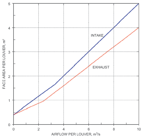
| Less than 7000 cfm3300 L/s | See Figure 1.0 |
| Exhaust | |
| 5000 cfm 2400 L/s and greater | 2.5 |
| Less than 5000 cfm 2400 L/s | See Figure 1.0 |
| Filters | |
| Panel filters | 1 to 4 |
| Viscous impingement | |
| Dry-type, extended-surface | Duct velocity |
| Flat (low efficiency) | |
| Pleated media (intermediate efficiency) | Up to 3.8 |
| HEPA | 1.3 |
| Renewable media filters | |
| Moving-curtain viscous impingement | 2.5 |
| Moving-curtain dry media | 1 |
| Electronic air cleaners | Ionizing type |
| Heating Coils | |
| Steam and hot water | 2.5 to 5 1 min., 8 max. |
| Electric | |
| Open wire | Refer to mfg. data |
| Finned tubular | Refer to mfg. data |
| Dehumidifying Coils | 2 to 3 |
| Air Washers | |
| Spray type | Refer to mfg. data |
| Cell type | Refer to mfg. data |
| High-velocity spray type | 6 to 9 |
| Parameters for Figure | Intake Louver |
Exhaust Louver |
| Min. free area (1220 mm2 test section | 45 |
45 |
| Water penetration, mL/(m2 · 0.25 h) | Negligible (< 0.3) |
N/A |
| Max. static Pressure Drop, Pa | 35 |
60 |
Figure 1.0 (Table + Chart Data) Criteria for Louver Sizing ( 2017F, Ch 21, Fig. 19)
Adapted from: ASHRAE Pocket Guide for Air Conditioning, Heating, Ventilation, Refrigeration SI 9th Edition
Related:
