Types of Broaching Tools Optimal Cutting Equations
Types of Broaching Tools Optimization Cutting Equations
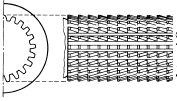
Typical types of broach tooling are illustrated below. Before the broaching process, a broach access hole or feature is created at a desired and optimal size to facilitate access for the broach tool and minimal material removal requirements.
| Description | Broach Illustration |
| Gear Broach- Internal |  |
| Rectangular Broach |  |
| Double Keyway Broach |  |
| Single Keyway Broach |  |
| Internal Helical Groove Broach |  |
| Round / Diametric Broach |  |
| Round / Diametric Broach |  |
| Square Broach |  |
Optimal Cutting Equations
Broach Tool Teeth Pitch:
The optimal broach tool pitch teeth should be specified by the depth and length of the tool cut, as well as the force required to operate the broaching tool by the machine tool.
Broach Tool Pitch Formulas Equation:
| Minimum Pitch = | |
| Allowable Pitch = |  |
Where:
L = Length of cut by broaching tool (inches)
d = For External broaching, depth of cut per tooth as given by Table A
d = For Internal broaching, depth of cut per tooth per side or one-half difference in diameters of successive teeth for round broach tools.
F = Constant
Brittle material, F = 3 - 4 roughing operations, use 6 for
finishing operations.
Ductile material, F = 4 - 7 roughing operations, use
8 for finishing operations.
b = Width of cut removed by broaching tool (inches)
P = Pressure (tons/in2), depth of cut X width of cut ( inches) see Table B
T = Rated capacity of broaching machine (tons)
Design Data Surface Broach Tools
Table A
| Material to be Broached | Depth of Cut per Tooth, Inch | Face Angle or Rake, Degrees | Clearance Angle, Degrees | ||
| Roughing a | Finishing | Roughing | Finishing | ||
| Steel, High Tensile Strength | 0.0015–0.002 | 0.0005 | 10–12 | 1.5–3 | 0.5–1 |
| Steel, Medium Tensile Strength | 0.0025–0.005 | 0.0005 | 14–18 | 1.5–3 | 0.5–1 |
| Cast Steel | 0.0025–0.005 | 0.0005 | 10 | 1.53 | 0.5 |
| Malleable Iron | 0.0025–0.005 | 0.0005 | 7 | 1.5–3 | 0.5 |
| Cast Iron, Soft | 0.006 –0.010 | 0.0005 | 10–15 | 1.5–3 | 0.5 |
| Cast Iron, Hard | 0.003 –0.005 | 0.0005 | 5 | 1.5–3 | 0.5 |
| Zinc Die Castings | 0.005 –0.010 | 0.0010 | 12 | 5 | 2 |
| Cast Bronze | 0.010 –0.025 | 0.0005 | 8 | 0 | 0 |
| Wrought Aluminum Alloys | 0.005 –0.010 | 0.0010 | 15 | 3 | 1 |
| Cast Aluminum Alloys | 0.005 –0.010 | 0.0010 | 12 | 3 | 1 |
| Magnesium Die Castings | 0.010 –0.015 | 0.0010 | 20 | 3 | 1 |
Broaching Pressure P
Table B
| Material to be Broached | Depth d of Cut per Tooth, Inch |
Pressure P, Side-cutting Broaches |
||||
| 0.024 | 0.010 | 0.004 | 0.002 | 0.001 | ||
Pressure P in Tons per Square Inch |
||||||
| Steel, High Ten. Strength | … | … | … | 250 | 312 | 200-.004″cut |
| Steel, Med. Ten. Strength | … | … | 158 | 185 | 243 | 143-.006″cut |
| Cast Steel | … | … | 128 | 158 | … | 115-.006″ cut |
| Malleable Iron | … | … | 108 | 128 | … | 100-.006″ cut |
| Cast Iron | … | 115 | 115 | 143 | … | 115-.020″ cut |
| Cast Brass | … | 50 | 50 | … | … | ............ |
| Brass, Hot Pressed | … | 85 | 85 | … | … | ............ |
| Zinc Die Castings | … | 70 | 70 | … | … | ............ |
| Cast Bronze | 35 | 35 | … | … | … | ............ |
| Wrought Aluminum | … | 70 | 70 | … | … | ............ |
| Cast Aluminum | … | 85 | 85 | … | … | ............ |
| Magnesium Alloy | 35 | 35 | … | … | … | ............ |