Continuous Casting Process Review
Continuous Casting Process Review
Continuous casting, much like centrifugal molding, produces sheets or beams which may undergo further fabrication.Continuous casting involves forcing a melted metal through an open-ended mold. Heat is extracted and metal exits the mold as a solid fabricated sheet. Molds are commonly made of graphite.
Continuous Casting Manufacturing Process
Molds or "dies" last several weeks, after which graphite must be reworked to original specifications. Metal melting points impose severe restrictions on mold design. Consequently, iron is difficult while aluminum and its alloys are relatively easy to process. The technique already is well-automated and is used to fabricate aluminum and copper alloys, but only on very special applications for iron.
Starting a continuous casting machine involves placing a dummy bar (essentially a curved metal beam) up through the spray chamber to close off the base of the mould. Metal is poured into the mould and withdrawn with the dummy bar once it solidifies. It is extremely important that the metal supply afterwards be guaranteed to avoid unnecessary shutdowns and restarts, known as 'turnarounds'. Each time the caster stops and restarts, a new tundish is required, as any uncast metal in the tundish cannot be drained and instead freezes into a 'skull'. Avoiding turnarounds requires the meltshop, including ladle furnaces (if any) to keep tight control on the temperature of the metal, which can vary dramatically with alloying additions, slag cover and deslagging, and the preheating of the ladle before it accepts metal, among other parameters. However, the cast rate may be lowered by reducing the amount of metal in the tundish (although this can increase wear on the tundish), or if the caster has multiple strands, one or more strands may be shut down to accommodate upstream delays. Turnarounds may be scheduled into a production sequence if the tundish temperature becomes too high after a certain number of heats or the service lifetime of a non-replaceable component (i.e., the submerged entry nozzle (SEN) in a thin-slab casting machine) is reached.
Many continuous casting operations are now fully computer-controlled. Several electromagnetic, thermal, or radiation sensors at the ladle shroud, tundish and mould sense the metal level or weight, flow rate and temperature of the hot metal, and the programmable logic controller (PLC) can set the rate of strand withdrawal via speed control of the withdrawal rolls. The flow of metal into the moulds can be controlled via two methods:
By slide gates or stopper rods at the top of the mould shrouds
If the metal is open-poured, then the metal flow into the moulds is controlled solely by the internal diameter of the metering nozzles. These nozzles are usually interchangeable.
Overall casting speed can be adjusted by altering the amount of metal in the tundish, via the ladle slide gate. The PLC can also set the mould oscillation rate and the rate of mould powder feed, as well as the flow of water in the cooling sprays within the strand. Computer control also allows vital casting data to be transmitted to other manufacturing centres (particularly the steelmaking furnaces), allowing their work rates to be adjusted to avoid 'overflow' or 'underrun' of product.
- Continuously cast sections capability
Casting machines are designated to be billet, bloom or slab casters. - Slab casters tend to cast sections that are much wider than thick:
- Conventional slabs lie in the range 100–1600 mm wide by 180–250 mm thick and up to 12 m long with conventional casting speeds of up to 1.4 m/minute; however slab widths and casting speeds are currently increasing.
- Wider slabs are available up to 3250×150 mm
- Thick slabs are available up to 2200×450 mm at a specific steel facility, generically ranging typically from 200mm to 300mm
- Thin slabs (low-carbon steel): 1680×50 mm at a specific facility, generically ranging from 40mm to 110mm thick depending on an individual machine's design
- Conventional bloom casters cast sections above 200×200 mm. The bloom length can vary from 4 to 10 m
- Billet casters cast smaller section sizes, such as below 200 mm square, with lengths up to 12 m long. Cast speeds can reach up to 4 m/minute.
- Rounds: either 500 mm or 140 mm in diameter
- Conventional beam blanks: look similar to I-beams in cross-section; 1048×450 mm or 438×381 mm overall
- Near net shape beam blanks: 850×250 mm overall
- Strip: 2–5 mm thick by 760–1330 mm wide

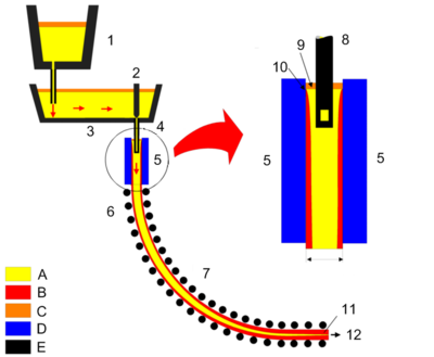
Continuous casting.
1: Ladle.
2: Stopper.
3: Tundish.
4: Shroud.
5: Mold.
6: Roll support.
7: Turning zone.
8: Shroud.
9: Bath level.
10: Meniscus.
11: Withdrawal unit.
12: Slab.
A: Liquid metal. B: Solidified metal.
C: Slag.
D: Water-cooled copper plates.
E: Refractory material.