Related Resources: manufacturing
Insert Cutter Radius Compensation
Manufacturing Engineering and Design
Machining Insert cutters are removable cutting tips, which means they are not brazed or welded to the tool body. Insert cutters can be exchanged, and often also rotated or flipped, without disturbing the overall geometry of the tool (effective diameter, tool length offset, etc.). This saves time in manufacturing by allowing fresh cutting edges to be presented periodically without the need for tool grinding, setup changes, or entering of new values into a CNC program.
Insert Cutter Radius Compensation per. Specification ANSI B212.3
All dimensions are in inches.
|
Square Profile Insert Cutter
|
||||||
|
B Style
Also applies to R Style |
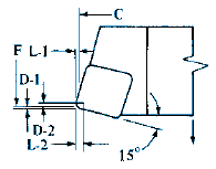 |
Turning 15° Lead Angle
|
||||
|
Rad.
|
L-1
|
L-2
|
D-1
|
D-2
|
||
|
1⁄64
|
.0035
|
.0191
|
.0009
|
.0110
|
||
|
1⁄32
|
.0070
|
.0383
|
.0019
|
.0221
|
||
|
3⁄64
|
.0105
|
.0574
|
.0028
|
.0331
|
||
|
1⁄16
|
.0140
|
.0765
|
.0038
|
.0442
|
||
|
D Style
Also applies to S Style |
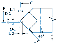 |
Turning 45° Lead Angle
|
||||
|
Rad.
|
L-1
|
L-2
|
D-1
|
D-2
|
||
|
1⁄64
|
.0065
|
.0221
|
.0065
|
0
|
||
|
1⁄32
|
.0129
|
.0442
|
.0129
|
0
|
||
|
3⁄64
|
.0194
|
.0663
|
.0194
|
0
|
||
|
1⁄16
|
.0259
|
.0884
|
.0259
|
0
|
||
|
K Style
|
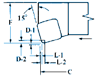 |
Facing 15° Lead Angle
|
||||
|
Rad.
|
L-1
|
L-2
|
D-1
|
D-2
|
||
|
1⁄64
|
.0009
|
.0110
|
.0035
|
.0191
|
||
|
1⁄32
|
.0019
|
.0221
|
.0070
|
.0383
|
||
|
3⁄64
|
.0028
|
.0331
|
.0105
|
.0574
|
||
|
1⁄16
|
.0038
|
.0442
|
.0140
|
.0765
|
||
|
Triangle Insert Cutter Profile
|
||||||
|
G Style
|
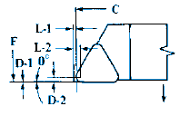 |
Turning 0° Lead Angle
|
||||
|
Rad.
|
L-1
|
L-2
|
D-1
|
D-2
|
||
|
1⁄64
|
.0114
|
.0271
|
0
|
.0156
|
||
|
1⁄32
|
.0229
|
.0541
|
0
|
.0312
|
||
|
3⁄64
|
.0343
|
.0812
|
0
|
.0469
|
||
|
1⁄16
|
.0458
|
.1082
|
0
|
.0625
|
||
|
B Style
Also applies to R Style |
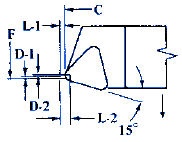 |
Turning and Facing 15° Lead Angle
|
||||
|
Rad.
|
L-1
|
L-2
|
D-1
|
D-2
|
||
|
1⁄64
|
.0146
|
.0302
|
.0039
|
.0081
|
||
|
1⁄32
|
.0291
|
.0604
|
.0078
|
.0162
|
||
|
3⁄64
|
.0437
|
.0906
|
.0117
|
.0243
|
||
|
1⁄16
|
.0582
|
.1207
|
.0156
|
.0324
|
||
|
F Style
|
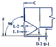 |
Facing 90° Lead Angle
|
||||
|
Rad.
|
L-1
|
L-2
|
D-1
|
D-2
|
||
|
1⁄64
|
0
|
.0156
|
.0114
|
.0271
|
||
|
1⁄32
|
0
|
.0312
|
.0229
|
.0541
|
||
|
3⁄64
|
0
|
.0469
|
.0343
|
.0812
|
||
|
1⁄16
|
0
|
.0625
|
.0458
|
.1082
|
||
|
J Style
|
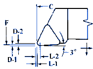 |
Turning and Facing 3° Lead Angle
|
||||
|
Rad.
|
L-1
|
L-2
|
D-1
|
D-2
|
||
|
1⁄64
|
.0106
|
.0262
|
.0014
|
.0170
|
||
|
1⁄32
|
.0212
|
.0524
|
.0028
|
.0340
|
||
|
3⁄64
|
.0318
|
.0786
|
.0042
|
.0511
|
||
|
1⁄16
|
.0423
|
.1048
|
.0056
|
.0681 |
||
L-1 and D-1 over sharp point to nose radius; and L-2 and D-2 over sharp point to center of nose radius. The D-1 dimension for the B, E, D, M, P, S, T, and V style tools are over the sharp point of insert to a sharp point at the intersection of a line on the lead angle on the cutting edge of the insert and the C dimension. The L-1 dimensions on K style tools are over the sharp point of insert to sharp point intersection of lead angle and F dimensions.