Design of Load Carrying Shaft With One Pulley & Supported by Two Bearings
Mechanics and Machines Calculations Menu
Design of Load Carrying Shaft With One Pulley & Supported by Two Bearings
A belt pulley is keyed to the shaft, midway between the supporting bearings kept at 1000 mm apart. The shaft transmits 20 KW power at 400 rpm. Pulley has 400 mm diameter. Angle of wrap of belt on pulley is 1800 and the belt tensions act vertically downwards. The ratio of belt tensions = 2.5.
The shaft is made of steel having ultimate tensile stress and yield stress of 400 Mpa and 240 Mpa respectively. Use ASME code to design the diameter of shaft with combined fatigue and shock factors in bending and torsion as 1.5 and 1.25 respectively.
Machine Design Diagram:
Step I: Applying ASME code to find ![]()
Where:
![]() = 0.3 x Syt
= 0.3 x Syt
OR
![]() = 0.18 x Sut
= 0.18 x Sut
Whichever of the above two equations are minimum;
![]() = 0.3 x 240 = 72 Mpa
= 0.3 x 240 = 72 Mpa
OR
![]() = 0.18 x 400 = 72 Mpa
= 0.18 x 400 = 72 Mpa
Since, the pulleys are keyed to the shaft therefore, reducing smaller value by 25%.
![]() = 0.75 x 72 = 54 Mpa
= 0.75 x 72 = 54 Mpa
Step II : Torque Transmitted :
Using the relationship:
![]()
![]()
Since torque is transmitted by a belt drive:
Torque = (T1 - T2) r
477464.829 = (T1 - T2) x 200
(T1 - T2) = 2387.3241
also,
![]()
(2.5 T2 - T2) = 2387.3241
T2 = 1591.5494,
Hence T1 = 3978.8735 N
Step III - Find maximum B.M. i.e.; M:

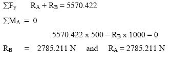
Since belt tensions act vertically downwards, the vertical load at the center of the shaft becomes (T1 + T2 ) in the downward direction.
Therefore:

Bending moment Calculations:
B.M at A = 0
B.M at C = 2785.211 x 500 =1392605.644 Nmm
B.M at B = 0
Maximum Bending Moment (Mmax) = 1392605.644 Nmm
Step IV - Using the final formula as per theory mentioned we find shaft diameter ‘d’
![]()
![]()
d3 = 204897.027
d = 58.9539 mm
