Related Resources: mechanics machines
Power Screws Design Equation and Calculator

Preview: Power Screws Torque Design Calculator
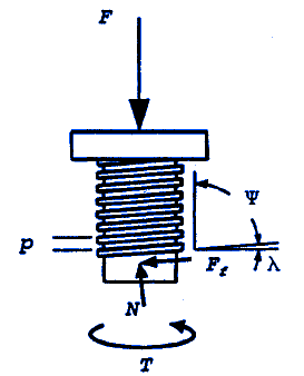
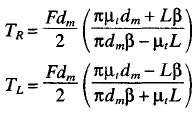
Under static equilibrium conditions, the screw rotates at a constant speed in response to the input torque T shown in the free-body diagram above. In addition, the load force F, normal force N, and sliding friction force Ff act on the power screw. tive motion. The friction force opposes relative motion. Therefore, the direction of the friction force Ff will reverse when the screw translates in the direction of the load rather than against it. The torques required to raise the load TR (i.e., move the screw in the direction opposing the load) and to lower the load TL are:

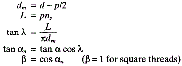
Where:

The thread geometry parameter β includes the effect of the flank angle α as it is projected normal to the thread and as a function of the lead angle. For general-purpose single-start Acme threads, α is 14.5 degrees and β is approximately 0.968, varying less than 1 percent for diameters ranging from 1/4 in to 5 in and thread spacing ranging from 2 to 16 threads per inch. For square threads, β = 1.
In many applications, the load slides relative to a collar, thereby requiring an additional input torque Tc:
Tc = F µc dc / 2
Ball and tapered-roller thrust bearings can be used to reduce the collar torque.
The starting torque is obtained by substituting the static coefficients of friction into the above equations. Since the sliding coefficient of friction is roughly 25 percent less than the static coefficient, the running torque is somewhat less than the starting torque. For precise values of friction coefficients, specific data should be obtained from the published technical literature and verified by experiment.
Power screws can be self-locking when the coefficient of friction is high or the lead is small, so that π µt dm > L or, equivalently, µf > tan λ. When this condition is not met, the screw will self-lower or overhaul unless an opposing torque is applied.
A measure of screw efficiency η can be formulated to compare the work output Wo with the work input Wi:
![]()
where T is the total screw and collar torque. Similarly, for one revolution or 2π radians and screw translation L,
η = F L / ( 2 π T )
Screw manufacturers often list output travel speed V, in in/min, as a function of required motor torque T in lbf · in, operating at n r/min, to lift the rated capacity F, in lbf. The actual efficiency for these data is therefore
η = F V / ( 2 π n T )
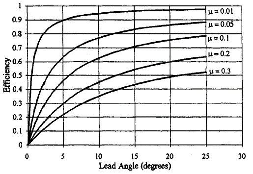
Efficiency of a square-threaded power screw with respect to lead angle X, as shown in the table below, is obtained from
η = ( 1 - µ tan λ ) / ( 1 + µ cos λ )

Screw efficiency η vs. thread lead angle λ.
Note the importance of proper lubrication. For example, for λ = 10 degrees and µ = 0.05, η is over 75 percent. However, as the lubricant becomes contaminated with dirt and dust or chemically breaks down over time, the friction coefficient can increase to µ = 0.30, resulting in an efficiency η = 35 percent, thereby doubling the torque, horsepower, and electricity requirements.
Where:
F = Axial Force applied, lbf
dm = Mean Diameter, inches
d = major diameter, inches
µf = Coefficient of thread friction
L = Lead of thread
β = Thread geometry parameter
p = Thread pitch, inches
ns = Number of thread starts
α = Thread flank angle, degrees
αn = Normalized thread flank angle, degrees
λ = Lead angle, degrees
V = in/min
References:
Standard Handbook of Machine Design, Second Edition, Shigley & Mischke