Related Resources: mechanics machines
Shaft Couplings Design Equation and Calculator

Preview: Solid Rigid Couplings Design Calculator
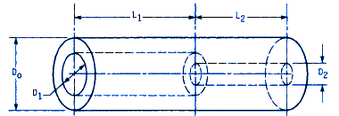
The maximum shear stress occurs at the outer radius of the coupling and at the interface of the two bores. This stress can be derived from the torsion formula:
τmax = T Do / 2 J
Where J, the polar second moment of intertia is:
J = π / 32 ( D4o - D4i )
The coupling must be sized so that, typically, the stress does not exceed 10 percent of the ultimate tensile strength of the material.
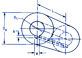
Other factors to consider are the length of engagement into the coupling. The shear stress over the keyway must not exceed the allowable shear stress as given above. The centroidal radius is:
Rc = 0.5 * ( Do / 2 + Di / 2 + h )
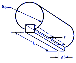
The centroid of the bearing area is at radius (Di + h) / 2. If the transmitted torque is T, then the compressive force F is 2 T / (Di + h). The bearing stress σb is:
σb = F / A = 4 T / ( w L (Di + h) )
The allowable compressive stress from distortion energy theory of failure is σall = τall / 0.577. Combining this equation σb with gives:
τall = [ 0.577 ( 4 ) T ] / [ w L (Di + h) ]
Next, the length of key stock, for keyed shafts, must be examined to keep its shear loading from exceeding the allowable shear stress. Referring to the equation for σb , we note that the shear force is:
F = T / τ /2) = 2 T / Di Therefore the average shear stress is
τ = F / A = ( 2 T ) / ( w L Di )


Both keys must be checked, although experience has shown that small diameter shafts are more prone to failure of the key and keyway when these precautions are not followed because of their normally smaller key width and length of engagement.
|
Maximum Allowable Shear Stress
|
|
|
Material
|
Stress, psi
|
|
Aluminum
|
4000
|
|
Cast Iron
|
4500
|
|
Ductile Iron
|
6000
|
|
Brass
|
3500
|
|
Powered Iron
|
4000 |
|
Steel
|
8000
|
Where:
T = Torque, lb-in
Do = Diameter Outer, in
Di = Diameter inner, in
J = Polar Second Moment of Inertia, in3
Rc= Centroidal radius or distance, in
F = Compressive Force, lbf
A = Cross Sectional Area (in2)
w = Width, in
L = Length, in
h = Keyway height, in
τall = Compresive Shear Stress, psi
τ = Shear Stress, psi
Contributed by:
Harsh Patel
India Institute of Technology
India, New Delhi
References:
ISO R773, Rectangular or Square Parallel Keys and Their Corresponding Keyways, 1969.
JISB 1301, Bore and Keyway Tolerances.
AGMA Standard 514-02. 1971,f Load Classification and Service Factors for Flexible Couplings.
DIN 74(V Flexible (Shaft) Couplings; Dimensions, Nominal Torque.
AGMA Standard 515.02-1977, Balance Classification for Flexible Couplings.
ISO 1940,1 Balance Quality of Rotating Rigid Bodies. 1973.
Standard Handbook of Machine Design, Joseph E. Shigley 1996
Charles R. Mischke
Second Edition