Carnot Cycle Review Thermodynamics
Thermodynamics Directory | Heat Transfer Directory
Carnot Cycle Review
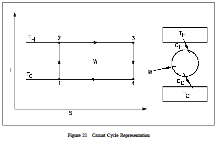
The carnot principal is best demonstrated with a simple cycle (shown in Figure 21) and an example of a proposed heat power cycle. The cycle consists of the following reversible processes.
1-2: adiabatic compression from TC to TH due to work performed on fluid.
2-3: isothermal expansion as fluid expands when heat is added to the fluid at temperature TH.
3-4: adiabatic expansion as the fluid performs work during the expansion process and temperature drops from TH to TC.
4-1: isothermal compression as the fluid contracts when heat is removed from the fluid at temperature TC.
This cycle is known as a Carnot Cycle. The heat input (QH) in a Carnot Cycle is graphically represented on Figure 21 as the area under line 2-3. The heat rejected (QC) is graphically represented as the area underline 1-4. The difference between the heat added and the heat rejected is the network (sum of all work processes), which is represented as the area of rectangle 1-2-3-4.

The efficiency ![]() of the cycle is the ratio of the network of the cycle to the heat input to the cycle. This ratio can be expressed by the following equation.
of the cycle is the ratio of the network of the cycle to the heat input to the cycle. This ratio can be expressed by the following equation.

Equation 1-23 shows that the maximum possible efficiency exists when TH is at its largest possible value or when TC is at its smallest value. Since all practical systems and processes are really irreversible, the above efficiency represents an upper limit of efficiency for any given system operating between the same two temperatures. The system’s maximum possible efficiency would be that of a Carnot efficiency, but because Carnot efficiencies represent reversible processes, the actual system will not reach this efficiency value. Thus, the Carnot efficiency serves as an unattainable upper limit for any real system’s efficiency. The following example demonstrates the above principles.
Example 1: Carnot Efficiency
An inventor claims to have an engine that receives 100 Btu of heat and produces 25 Btu of useful work when operating between a source at 140°F and a receiver at 0°F. Is the claim a valid claim?

Claimed efficiency = 25/100 = 25%
Therefore, the claim is invalid.
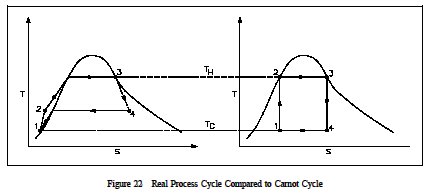
The most important aspect of the second law for our practical purposes is the determination of maximum possible efficiencies obtained from a power system. Actual efficiencies will always be less than this maximum. The losses (friction, for example) in the system and the fact that systems are not truly reversible preclude us from obtaining the maximum possible efficiency. An illustration of the difference that may exist between the ideal and actual efficiency is presented in Figure 22 and the following example.
Example 2: Actual vs. Ideal Efficiency
The actual efficiency of a steam cycle is 18.0%. The facility operates from a steam source at 340°F and rejects heat to atmosphere at 60°F. Compare the Carnot efficiency to the actual efficiency.

Solution:
˙
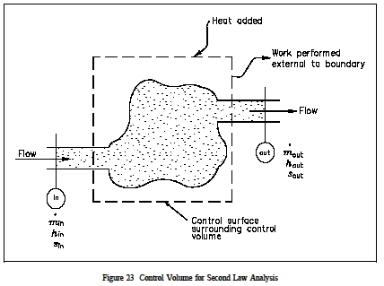
An open system analysis was performed using the First Law of Thermodynamics. These conditional law problems are treated in much the same manner; that is, an isolated, closed, or open system is used in the analysis depending upon the types of energy that cross the boundary. As with the first law, the open system analysis usingthese cond law equations is the more general case, with the closed and isolated systems being "special" cases of the open system. The solution to second law problems is very similar to the approach used in the first law analysis. Figure 23 illustrates the control volume from the view point of the second law. In this diagram, the fluid moves through the control volume from section into section out while work is delivered external to the control volume. We assume that the boundary of the control volume is at some environmental temperature and that all of the heat transfer (Q) occurs at this boundary. We have already noted that entropy is a property, so it may be transported with the flow of the fluid into and out of the control volume, just like enthalpy or internal energy. The entropy flow into the control volume resulting from mass transport is, therefore, and the entropy flow out of the control volume is, assuming that the properties are uniform at sections in and out. Entropy may also be added to the control volune because of heat transfer at the boundary of the control volume.

A simple demonstration of the use of this form of system in second law analysis will give the student a beter understanding of its use.
Example 3:
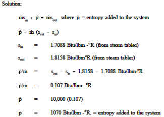
Open System Second Law Steam enters the nozzle of a steam turbine with a velocity of 10ft/sec at a pressure of 100 psia and temperature of 500F at the nozzle discharge. The pressure and temperature are 1 atm at 300F. What is the increase in entropy for the system if the mass flow rate is 10,000lbm/hr?

It should always be kept in mind that the Second Law of Thermodynamics gives an upper limit (which is never reached in physical systems) to how efficiently a thermodynamic system can perform. A determination of that efficiency is as simple as knowing the inlet and exit temperatures of the overall system (one that works in a cycle) and applying Carnot’s efficiency equation using these temperatures in absolute degrees.