Related Resources: calculators
V-Belt Classical Speed to Horsepower Formulas and Calculator for Cross Sections
Belt Drive Design and Engineering
Mechanical Gear Design and Engineering
V-Belt Classical Speed to Horsepower Ratings Formulas and Calculator for Cross Sections

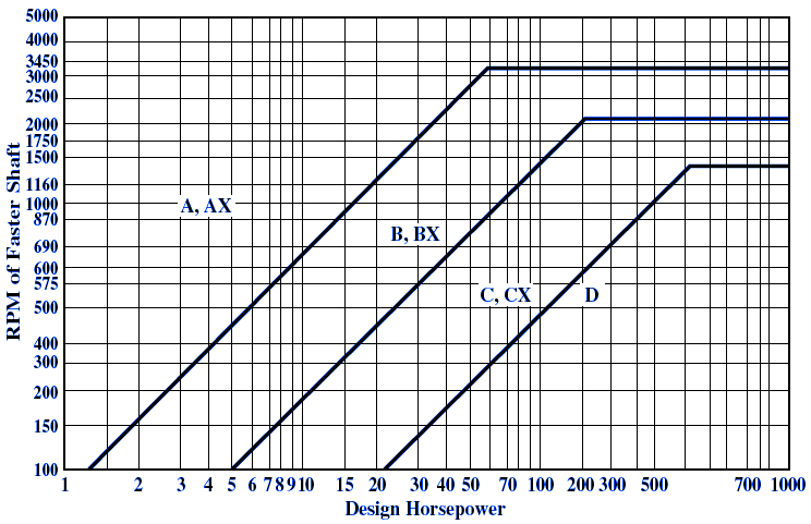
Cross Section Design Selection: Use the chart given below to determine if the V-belt cross section for any combination of design horsepower and speed of the faster shaft. When the intersection of the design horsepower and speed of the faster shaft falls near a line between two areas on the chart, the possibilities in both areas should be investigated. Special circumstances (such as space limitations) may lead to a choice of belt cross section different from that indicated in the chart.
Design HP = Basic Horsepower Rating x Service Factor
Basic Horsepower Rating Formulas
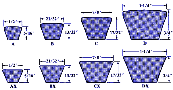
V-Belt Cross Section "A"
HP = dp rk [ 1.004 - 1.652 / dp - 1.5747 x 10⁻⁴ ( dp r )2 - 0.2126 log( dp r ) ] + 1.652 r ( 1 - 1 / KSR )
V-Belt Cross Section "AX"
HP = dp rk [ 1.462 - 2.239 / dp - 2.198 x 10⁻⁴ ( dp r )2 - 0.4238 log( dp r ) ] + 2.239 r ( 1 - 1 / KSR )
V-Belt Cross Section "B"
HP = dp rk [ 1.769 - 4.372 / dp - 3.081 x 10⁻⁴ ( dp r )2 - 0.3658 log( dp r ) ] + 4.372 r ( 1 - 1 / KSR )
V-Belt Cross Section "BX"
HP = dp rk [ 2.051 - 3.532 / dp - 3.097 x 10⁻⁴ ( dp r )2 - 0.5735 log( dp r ) ] + 3.532 r ( 1 - 1 / KSR )
V-Belt Cross Section "C"
HP = dp rk [ 3.325 - 12.07 / dp - 5.828 x 10⁻⁴ ( dp r )2 - 0.6886 log( dp r ) ] + 12.07 r ( 1 - 1 / KSR )
V-Belt Cross Section "CX"
HP = dp rk [ 3.272 - 6.655 / dp - 5.298 x 10⁻⁴ ( dp r )2 - 0.8637 log( dp r ) ] + 6.655 r ( 1 - 1 / KSR )
V-Belt Cross Section "D"
HP = dp rk [ 7.160 - 43.21 / dp - 1.384 x 10⁻⁴ ( dp r )2 - 1.454 log( dp r ) ] + 43.21 r ( 1 - 1 / KSR )
Where:
dp = pitch diameter of small sheave, in.
r = rpm of the faster shaft.
rk = r / 1000
KSR = speed ratio factor given in the accompanying Table below.
Speed Ratio Range = Dp / dp
Where:
Dp = Pitch of Large Sheave
dp = Pitch of Small Sheave
|
Speed Ratio Range
|
KSR
|
|
1.00 - 1.01
|
1.0000
|
|
1.02 - 1.04
|
1.0112
|
|
1.05 - 1.07
|
1.0226
|
|
1.08 - 1.10
|
1.0344
|
|
1.11 - 1.14
|
1.0463
|
|
1.15 - 1.20
|
1.0586
|
|
1.21 - 1.27
|
1.0711
|
|
1.28 - 1.39
|
1.0840
|
|
1.40 - 1.64
|
1.0972
|
|
> 1.64
|
1.1106
|

FPM to RPM Equation:
r = s / ( π d )
RPM to FPM Equation:
s = r π d
Where:
r = rpm
s = ft / min
d = diameter of pulley in ft
Related:
- Synchronous Timing Belt Tooth Section Dimensions Table per ANSI / RMA IP-24
- Synchronous Timing Belt Pulley Dimensions Table per ANSI / RMA IP-24
- Synchronous Timing Belt Lengths and Tolerances per. ANSI RMA IP-24 Table
- Service Factors Synchronous Timing Belts
- Synchronous Timing Belt Standard Widths and Tolerances Table
- Synchronous Belt Standard Pulley Diameters ANSI/RMA IP-24 Table
- Timing Belt Pulley Mechanical Tolerances per. ANSI RMA IP-24
References:
ANSI / RMA IP-24