Electrical Discharge Machining ( EDM ) Design Considerations Process Capabilities
Electrical Discharge Machining, EDM is one of the most accurate manufacturing processes available for creating complex or simple shapes and geometries within parts and assemblies. EDM works by eroding material in the path of electrical discharges that form an arc between an electrode tool and the work piece. EDM manufacturing is quite affordable and a very desirable manufacturing process when low counts or high accuracy is required. Turn around time can be fast and depends on manufacturer back log.
The EDM system consists of a shaped tool or wire electrode, and the part. The part is connected to a power supply. Sometimes to create a potential difference between the work piece and tool, the work piece is immersed in a dielectric (electrically non conducting fluid which is circulated to flush away debris.
 |
|---|
The cutting pattern is usually CNC controlled. Many EDM machine electrodes can rotate about two-three axis allowing for cutting of internal cavities. This makes EDM a highly capable manufacturing process.
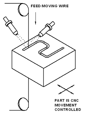
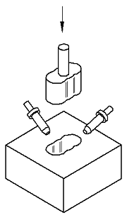
EDM comes in two basic types: wire and probe (die sinker). Wire EDM is used primarily for shapes cut shapes through a selected part or assembly. With a wire EDM machine, if a cutout needs to be created, an initial hole must first be drilled in the material, then the wire can be fed through the hole to complete the machining. Sinker (die sinking EDM's are generally used for complex geometries where the EDM machine uses a machined graphite or copper electrode to erode the desired shape into the part or assembly. Sinker EDM can cut a hole into the part without having a hole pre-drilled for the electrode.
EDM Power System. The discharge energy during EDM is provided by a direct current pulse power generator. The EDM power system can be classified into RC, LC, RLC, and transistorized types. The transistorized EDM power systems provide square waveform pulses with the pulse on-time usually ranging from 1 to 2000 msec, peak voltage ranging from 40 to 400V, and peak discharge current ranging from 0.5 to 500 A. With the RC, LC, or RLC type power system, the discharge energy comes from a capacitor that is connected in parallel with the machining gap. As a result of the low impedance of plasma channel, the discharge duration is very short (less than 5 msec), and the discharge current is very high, up to 1000 A. The peak voltage is in the same range of transistorized power systems.
The transistorized power systems are usually used in die-sinking EDM operations because of their lower tool wear. Capacitive power systems are used for small hole drilling, machining of advanced materials, and micro-EDM because of higher material removal rate and better process stability. WEDM power generator usually is a transistor-controlled capacitive power system that reduces the wire rupture risk. In this power system, the discharge frequency can be controlled by adjusting the on-time and off time of the transistors that control the charging pulse for the capacitor connected in parallel with the machining gap.
Key EDM System Components: The machining gap between tool and work piece during EDM must be submerged in an electrically nonconductive dielectric fluid. In die-sinking EDM, kerosene is often used as a dielectric fluid because it provides lower tool wear, higher accuracy, and better surface quality. Deionized water is always used as a dielectric fluid in WEDM to provide a larger gap size and lower wire temperature in order to reduce the wire rupture risk. This fluid also serves to flush debris from the gap and thus helps maintain surface quality.
Copper and graphite are commonly used as die-sinking EDM tool materials because of the high electrical conductivity and high melting temperature and the ease of being fabricated into complicated shapes. The wire electrode for WEDM is usually made of copper, brass, or molybdenum in a diameter ranging from 0.01 to 0.5 mm. Stratified copper wire coated with zinc brass with diameter of 0.25 mm is often used.
In the traditional die-sinking EDM process, the tool is fabricated into a required shape and mounted on a ram that moves vertically. The spark discharges can only occur under a particular gap size that determines the strength of electric field to break down the dielectric. A servo control mechanism is equipped to monitor the gap voltage and to drive the machine ram moving up or down to obtain a dischargeable gap size and maintain continuous sparking. Because the average gap voltage is approximately proportional to the gap size, the servo system controls the ram position to keep the average gap voltage as close as possible to a preset voltage, known as the servo reference voltage.
In a WED machine, the wire electrode is held vertically by two wire guides located separately above and beneath the work piece with the wire traveling longitudinally during machining. The work piece is usually mounted on an x-y table. The trajectory of the relative movement between wire and work piece in the x-y coordinate space is controlled by a CNC servo system according to a preprogrammed cutting passage. The CNC servo system also adjusts the machining gap size in real time, similar to the die sinking EDM operation. The dielectric fluid is sprayed from above and beneath the work piece into the machining gap with two nozzles.
 |
|---|
The power generators in WED machines usually are transistor-controlled RC or RLC systems that provide higher machining rate and larger gap size to reduce wire rupture risks. In some WED machines, the machining gap is submerged into the dielectric fluid to avoid wire vibration to obtain a better accuracy. The upper wire guide is also controlled by the CNC system in many WED machines. During machining, the upper wire guide and the x-y table simultaneously move along their own preprogrammed trajectories to produce a taper and/or twist surface on the work piece.
Advantages of EDM :
- Complex shapes that would otherwise be difficult to produce with conventional cutting tools
- Extremely hard material to very close tolerances
- Very small work pieces where conventional machining tools may damage the part from excess cutting tool pressure.
- There is no direct contact between tool and work piece. Therefore delicate sections and weak materials can be machined without any distortion.
Disadvantages of EDM :
- Relatively s low rate of material removal.
- Additional lead time and cost used for creating electrodes for ram/sinker EDM.
- Reproducing sharp corners on the workpiece is difficult due to electrode wear.
- Electrical power consumption is high.
- Material must be electrically conductive
Mechanical Design Considerations:
- Relax the surface-finish for the part, if feasible. This allows the manufacturer to produce the part with fewer passes, at a higher current level and a higher metal-removal rate.
- Design or prepare the part such that the amount of stock removed by EDM is relatively small. Use traditional machining techniques to remove the bulk of the stock with the finishing operations performed by EDM. This significantly reduces the amount of time and cost for each part.
- The EDM manufacturer should consider fixtures such that several parts can be stacked and machined simultaneously or a single part can have several EDM operations performed simultaneously.
- When existing holes are to be enlarged or reshaped by EDM, through holes are preferred to blind holes as they permit easier flow of dielectric fluid past the area being machined
- There will be some degree of materials exchange between the EDM wire / probe and the base material. Specify a cleaning procedure is galvanic corrosion is a concern.
- The minimum internal corner radius of cut feature will dictate the maximum wire diameter that can be used. Obviously, the wire diameter needs to be at less than double the minimum inside corner radius. However, one also has to account for the amount of final over cut, plus a small amount of "maneuvering" room, so that the CNC can generate the corner. This is analogous to CNC contour milling, in which accurate internal corner radii are generated by machine motion, rather than just plunging an end mill into a corner and accepting the result. Usually, "the bigger, the better" for wire diameters up to .010". It is important to note that the new "twin wire" machines can employ a different strategy for these conditions, however, most of us do not have this luxury. Recommendations for small diameter wires include:
- High Tensile Brass wire for .006" diameter
- Steel Core wire from .002" to .004" diameter
- Moly wire from .002" to .004"
- Tungsten wire from .0008" to .002"
Dimensional Accuracy (+/- 0.0005 inches per inch)
Feature Profile accuracy of .0003 is obtainable with cutting path
Features to feature true position of .002 is reasonable and down to .001 is possible when geometry requires removal and reattachment of wire.
Surface Finish (micro inches Features created by EDM have an "orange peal" appearance.
16 Ra is achievable, 64 or higher Ra is typical and less expensive.Wall Thickness
Min Wall Thickness (inches): 0.01 (over a 5" inch span) As always, consult with EDM vendor for specific capabilities.
Related