Related Resources: gears
Design of Square Key and Keyway (Wood Ruff) Stress, Shear and Torque
Machine Design Applications
Gear Design Data and Engineering
Design of Square Key and Keyway (Wood Ruff) Stress, Shear and Torque Equations and Calculator

ALL calculators require a Premium Membership
Related:
Torque Applied to Key
T = F ·(D/2)
or
F = T / (D/2)
Shear Stress
τ = T · Ks / [ W · L · (D / 2) · N ]
Factor of Safety
Fs = Ss / τ
Service Factors
Tight Fit Key / Key slot
Ks = Ka Kd / Kf
Slide Fit Key / Key slot
Ks = Ka Kd / Kw
Where:
τ = Shear Stress
Ss = Yield Stress of Key
T = Torque
F = Force
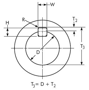
D = Shaft Diameter
W = Width
L = Length
Ks = Service Factor
Ka = Application Factor
Kd = Keyway application Factor
Kf = Fatigue Life Factor
Kw = Wear Life Factor
Fs = Design Factor of Safety
N = Number of Keys (same size)
Keyway application design factor Kd
| Coupling Design | Kd |
| Fixed (tight fit) while loaded | 1 |
| Sliding Fit - Axial motion along the shaft when unloaded. | 3 |
| Sliding along shaft with loading | 9 |
Application factors Ka
|
Application Factor Ka (DIN 3990-1)
|
||||
|
Driving Component Loading
|
Driven Component Loading
|
|||
|
Uniform
|
Light shock
|
Moderate Shock
|
Heavy Shock
|
|
| Uniform |
1.0
|
1.25
|
1.5
|
1.75
|
| Light Shock |
1.1
|
1.35
|
1.6
|
1.85
|
| Moderate Shock |
1.25
|
1.5
|
1.75
|
2.0
|
| Heavy Shock |
1.5
|
1.75
|
2.0
|
2.25 or Higher
|
Characteristics of the Driving Component
- Uniform: electric motor, steam or gas turbine (small, rarely occurring starting torques)
- Light Shock: electric motor, steam or gas turbine (large, frequently occurring starting torques)
- Moderate Shock: multiple cylinder internal combustion engines
- Heavy Shock: single cylinder internal combustion engines
Characteristics of the Driven Component
- Uniform: Steady load current generator, uniformly loaded conveyor belt or platform conveyor, worm conveyor, light lifts, packing machinery, feed drives for machine tools, ventilators, light-weight centrifuges, centrifugal pumps, agitators and mixers for light liquids or uniform density materials, shears, presses, stamping machines, vertical gear, running gear
- Light Shock: Non-uniformly (i.e. with piece or batched components) loaded conveyor belts or platform conveyors, machine-tool main drives, heavy lifts, crane slewing gear, industrial and mine ventilators, heavy centrifuges, centrifugal pumps, agitators and mixers for viscous liquids or substances of non-uniform density, multi-cylinder piston pumps, distribution pumps, extruders (general), calendars, rotating kilns, rolling mill stands, continuous zinc and aluminium strip mills, wire and bar mills
- Moderate Shock: Rubber extruders, continuously operating mixers for rubber and plastics, ball mills (light), wood-working machines (gang saws, lathes), billet rolling mills, lifting gear, single cylinder piston pumps
- Heavy Shock: Excavators (bucket wheel drives), bucket chain drives, sieve drives, power shovels, ball mills (heavy), rubber kneaders, crushers (stone, ore), foundry machines, heavy distribution pumps, rotary drills, brick presses, de-barking mills, peeling machines, cold strip c, e, briquette presses, breaker mills
Key distribution factor Km
|
Misalignment (in/in)
|
Misalignment of load factor Km
|
|||
|
1/2"
face width |
1"
face width |
2"
face width |
4"
face width |
|
|
0,001
|
1.0
|
1.0
|
1.0
|
1.5
|
|
0,002
|
1.0
|
1.0
|
1.5
|
2.0
|
|
0,004
|
1.0
|
1.5
|
2.0
|
2.5
|
|
0,008
|
1.5
|
2.0
|
2.5
|
3.0
|
Table showing fatigue life factors for splines Kf
| Torque cycles |
Fatigue life factor Kf
|
|
|
Unidirectional
|
Fully reversed
|
|
| 1,000 |
1.8
|
1.8
|
| 10,000 |
1.0
|
1.0
|
| 100,000 |
0.5
|
0.4
|
| 1,000,000 |
0.4
|
0.3
|
| 10,000,000 |
0.3
|
0.2
|
Table showing wear life factors for splines Kw
|
Life Revolutions of Key
|
Wear factor Kf
|
|
10,000
|
4.0
|
|
100,000
|
2.8
|
|
1 000,000
|
2.0
|
|
10,000,000
|
1.4
|
|
100,000,000
|
1.0
|
|
1000,000,000
|
0.7
|
|
10,000,000,000
|
0.5
|