O-Ring Installation Design and Specification Static Flange Application
The following chart gives typical gland dimensions for common o-ring sizes. Please consult with your o-ring manufacturer for custom or application specific requirements.
To use this document, first identify if you have an internal or external pressure gland requirement. From the chart below, identify your nominal o-ring desired size, then your o-ring gland depth requirements. After you have verified your nominal o-ring size functionality within your assembly, specify / design your o-ring groove/gland.
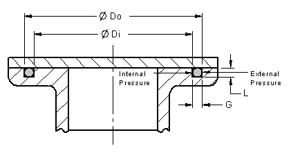
Male and Female O-Ring Gland / Groove Installation
For Internal Pressure tolerance the outermost surface of the o-ring gland / groove (Do) as follows:
For External Pressure tolerance the innermost surface of the o-ring gland / groove (Di) as follows:
NOTE: When possible, define tolerances as bi-lateral., i.e. ± .020, instead of +.040/-.000, or +.000/-.040. This maybe very helpfull to manufacturing in defining feature locations during programming operations for CNC machining operations. Where: Do = Outside diameter on gland outside surface |
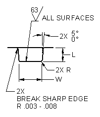
O-Ring Gland / Groove Detail
 |
Where: W = Width at bottom surface intersection of groove |
Typical O-Ring Static Seal Glands / Grooves
See "Gland / Groove Detail" above
O-Ring Nominal Diameter |
Actual Diameter (1) |
Gland Depth (L) |
Compression Actual |
Compression % |
Gland / Groove Width (W) Vacuum / Gases |
Gland / Groove Width (W) Liquids |
Groove Radius (R) |
1/16 |
.070± .003 |
.050 to .054 |
.013 |
19 to 32 |
.084 to .089 |
.101 to .107 |
.005 to .015 |
3/32 |
.103± .003 |
.074 to .080 |
.020 to .032 |
20 to 30 |
.120 to .125 |
.136 to .142 |
.005 to .015 |
1/8 |
.138± .004
|
.101 to .107 |
.028 to .042 |
20 to 30 |
.158 to .164 |
.177 to .187 |
.010 to .025 |
3/16 |
.210± .005
|
.152 to .162 |
.043 to .063 |
21 to 30 |
.239 |
.270 to .290 |
.020 to .035 |
1/4 |
.275± .006
|
.201 to .211 |
.058 to .080 |
21 to 29 |
.309 to .314 |
.342 to .362 |
.020 to .035 |
(1) May vary between different o-ring manufacturers
Related:
- Rubber Molding Design Guidelines and Review
- O-Ring, Design Considerations General
- O-Ring Installation, Design & Specification Gland (Groove) Sizes Static Cylindrical Applications
- O-Ring Installation Design & Specification For Dynamic / Reciprocating Applications
- O-Ring Installation Compressive Load vs Hardness Chart .070 Diameter ORing
- O-Ring Installation Compressive Load vs Hardness Chart .103 Diameter ORing
- O-Ring Installation Compressive Load vs Hardness Chart .139 Diameter ORing
- O-Ring Installation Compressive Load vs Hardness Chart .210 Diameter ORing
- O-Ring Installation Compressive Load vs Hardness Chart .275 Diameter ORing
