Plastic Injection Molding Design Considerations
Plastics Design Resources
Injection Molding Process Review
For more information see: Injection Molding Process Review
Injection Plastic Molding Design Guide.
Plastic injection molding is the primary process for manufacturing plastic parts. Plastic is known to be a very versatile and economical material that is used in many applications. Although the tooling is expensive, the cost per part is very low. Complex geometries are possible and limited only to mold manufacturability. Your computer monitor, mouse and keyboard are injection molded plastics.
Injection molding involves taking plastic in the form of pellets or granules and heating this material until a melt is obtained. Then the melt is forced into a split-die chamber/mold where it is allowed to "cool" into the desired shape. The mold is then opened and the part is ejected, at which time the cycle is repeated.
Design Considerations
Part design should include draft features (angled surfaces) to facilitate removal from the mold. Depending surface length draft angles down to half a degree are reasonable. Typical draft angles should be about 1 too 2 degrees for part surfaces not exceeding 5 inches. Dimensional tolerance specification will govern the part cost and manufacturability. If you have a small region of the part that needs higher tolerances, say the location of a critical feature used for alignment. DO NOT specify tight tolerance, instead design and plan for post molding processes such as machining using "assembly intent" fixturing.
Wall Thickness
Wall thickness for thin parts such as a soda bottle or ball point pen ink inserts are quite possible and economical. Thick wall sections are possible as well. Uneven wall thickness present challenges to the plastic molder manufacturer. Designing your part with uniform walls and cross section will simplify manufacturing and costing. At wall intersection or "tees" sinking will occur. Thick walls cool slower and greater shrinking will occur. Thin walls cool faster as thus, less shrinkage.
Radii and Corners
Maintain uniform wall thickness at corners. External and internal radius should share the same center point . External radii = internal radii + wall thickness. The minimum radii should not be less than 1/4 minimum wall thickness. Design for radii to be 1/2 to 3/4 of the nominal wall thickness. When significant stress is present, design in larger radius as larger radius distributes stress uniformly.
Ribs
Ribs should be 1/2 to 2/3 of the nominal wall thickness and less than 3 times thickness in height. Taper of 1 deg. is typical. Note: excess thickness promotes shrinkage. Excess rib height combined with taper will produce thin sections requiring extra fill time at the mold .
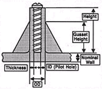
Bosses

-
Diameter = (Outside Diameter) \ (Inside Diameter) = 2 to 3
-
Thickness = 1/2 to 2/3 nominal wall thickness
-
Gusset Height = 2/3 Height
-
Height = Fastener minimum requirements
-
Taper = 1 deg. all around
-
Diameter Ratio should be minimum ratio of 2., this will reduce risk of failure.
Weld (Part) lines
location should be considered by design and the molder. Weld lines are formed at the mating of the flow fronts of the plastic during molding. The weld line area is more susceptible to cracks and stress failure.
Surface Finish (microinches) 64 or higher, depending on material, down to 7-16 is possible