Scissor Lift Jack Review & Equations
 |
Credits:
Calculations proof contributed by:
Show Canada, Inc.
Jean-Philippe Major
Jeffrey Trembley
Dominic Pellerin
Equations and Calculators updated: April 20, 2012
To submit an improved mathematical proof(s) (yes, we know parts of proof has an acedemic sign (-) imperfection) send a pdf with proper credits to webmaster-at-engineersedge.com.
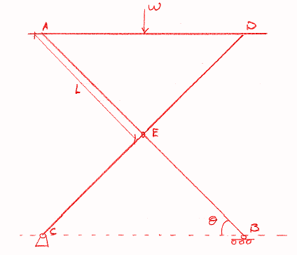
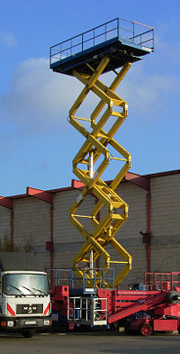
A scissor lift (jack) or mechanism is device used to extend or position a platform by mechanical means. The terms "Scissor" comes from the mechanism utilized which is configured with linked, folding supports in a crisscross 'X' pattern. The extension or displacement motion is achieved applying of force to one of the supports resulting and an elongation of the crossing pattern.
The force applied to extend the scissor mechanism may be hydraulic, pneumatic or mechanical (via a lead screw or rack and pinion system).
Design Equations for Scissor Lift:
For a scissor lift that has straight, equal-length arms, i.e. the distance from the horizontal-jack-screw attachment (or horizontal hydraulic-ram attachment) point to the scissors-joint is the same as the distance from that scissor-joint to the top load platform attachment.
Scissor Jack - Loading Applied at Bottom
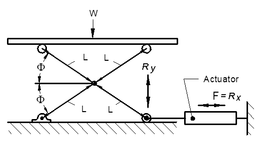
Open Scissor Lift Jack Force Bottom Load Calculator
Scissor Jack Equation With Load Applied At Center Pin:
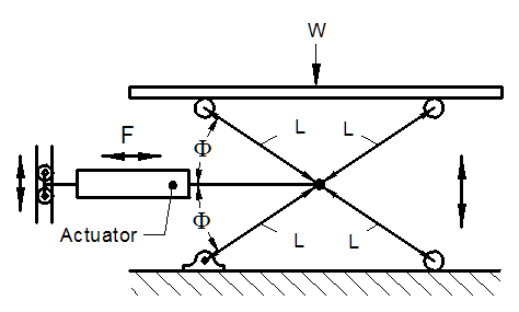
Open Scissor Lift Jack Force Center Load Calculator
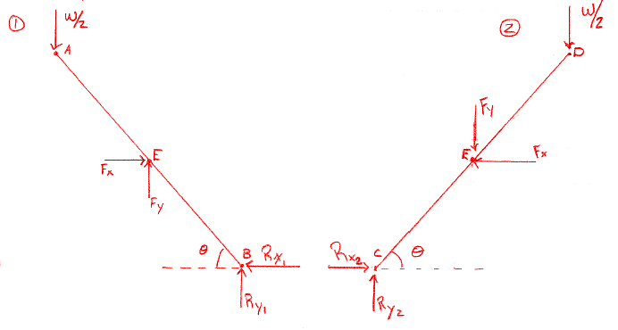
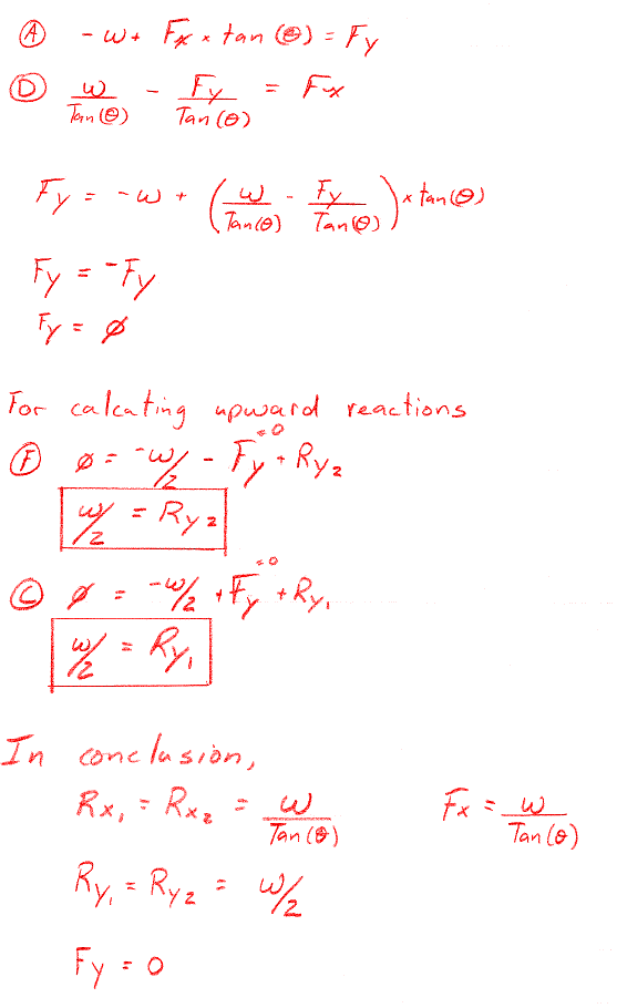
Free Body Diagrams:
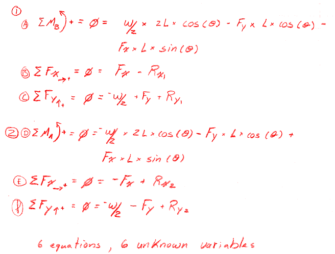
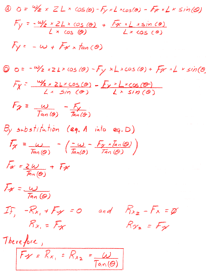
Static Equations
Related
- 2D CAD Static's Modeler and Loads Calculator
- AISC Steel structural Shapes Property Viewer
- Mechanism Creator and Editor Online Application
- Online Simple Loads Static's 2D Modeler Calculator Simple Loads and Reactions 2D Static's Modeler Calculator
- Hydraulic Scissor Lift Design Project
- Mathematical Analysis of Actuator Forces in a Scissor Lift
- Scissor Lift Design and Analysis Equations, Mathematical Analysis of Scissor Lifts
- Power Screw Design Equations and Calculator
