Related Resources: calculators
Bolt Torque and Clamping Force Formulas and Calculator per. JIS B 1083
Torque Design Menu
Torque Conversion Calculator
Strength of Materials
Bolt Preload Equations
Fastener Relation Between Torque and Clamping Force Formula and Calculator per. JIS B 1083
Preview Bolt Relation Between Torque and Clamping Force Formula and Calculator per. JIS B 1083

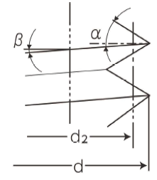
Bolt Thread nomenclature Figure 1
Relationship between the applied tightening torque and bolt preload Ff
Equation 1
Tf = Ts + Tw = K · Ff · d
Where:
Tf = fastener tightening torque
Tw = bearing surface torque
Ts = shank (threaded) portion torque
K = Torque coefficient (Eq. 2)
d = nominal diameter of the screw thread
Equation 2
K = 1 / ( 2 · d ) ( P / π + µs · d2 · sec α' + µw · Dw )
Where:
P = screw thread pitch
µs = coefficient of friction between threads
d2 = pitch diameter of the thread
µw = coefficient of friction between bearing surfaces
Dw = equivalent diameter of the friction torque bearing surfaces
α' = flank angle
at the ridge perpendicular section of the thread ridge
Equation 3
tan α' = tan (α) · cos(β)
Where:
α = thread half angle (30°, for example),
β = thread helix, or lead, angle.
Equation 4
β = l / ( 2πr )
Where:
r = thread radius (i.e., one-half
the nominal diameter d)
l = thread lead = P
When the bearing surface contact area is circular,
Equation 5
Dw = 2/3 · ( Do3 - Di3 ) / ( Do2 - Di2 )
Where:
Do = outside diameter bearing surface
contact area
Di = inside diameter bearing surface
contact area
Torques attributable to the threaded portion of a fastener, Ts, and bearing surfaces of a joint, Tw, are as follows:
Equation 6
Ts = Ff / 2 ( P / π + µs · d2 · sec α' )
Equation 7
Tw = ( Ff / 2 ) · µs · Dw
Where:
Ff, P, µ, d2, α′, µs, and Dw are as previously defined.
Equation 8
Tfy = K · Ffy · d
where the yield clamping force Ffy is given by:
Equation 9
Ffy = σy · As / { 1 + 3 [ 2 / dA ( P / π + µs · d2 ·sec(α') ) ]2 }
Where:
σy = yield point or proof stress of the bolt
As = stress area of the thread
dA = diameter of a circle having an area equal to the stress areaof the thread
Other varibles have been identified previously
Equation 10
dA = ( 4 As / π )1/2
Torque Coefficients K for Metric Hexagon Head
Bolt and Nut Coarse Screw Threads
JIS B 0205 (ISO 724) thread standard
Coefficient of Friction K |
||||||||||
Between Threads, µs |
Between Bearing Surfaces, µw |
|||||||||
0.08 |
0.10 |
0.12 |
0.15 |
0.20 |
0.25 |
0.30 |
0.35 |
0.40 |
0.45 |
|
0.08 |
0.117 |
0.130 |
0.143 |
0.163 |
0.195 |
0.228 |
0.261 |
0.293 |
0.326 |
0.359 |
0.10 |
0.127 |
0.140 |
0.153 |
0.173 |
0.206 |
0.239 |
0.271 |
0.304 |
0.337 |
0.369 |
0.12 |
0.138 |
0.151 |
0.164 |
0.184 |
0.216 |
0.249 |
0.282 |
0.314 |
0.347 |
0.380 |
0.15 |
0.153 |
0.167 |
0.180 |
0.199 |
0.232 |
0.265 |
0.297 |
0.330 |
0.363 |
0.396 |
0.20 |
0.180 |
0.193 |
0.206 |
0.226 |
0.258 |
0.291 |
0.324 |
0.356 |
0.389 |
0.422 |
0.25 |
0.206 |
0.219 |
0.232 |
0.252 |
0.284 |
0.317 |
0.350 |
0.383 |
0.415 |
0.448 |
0.30 |
0.232 |
0.245 |
0.258 |
0.278 |
0.311 |
0.343 |
0.376 |
0.409 |
0.442 |
0.474 |
0.35 |
0.258 |
0.271 |
0.284 |
0.304 |
0.337 |
0.370 |
0.402 |
0.435 |
0.468 |
0.500 |
0.40 |
0.285 |
0.298 |
0.311 |
0.330 |
0.363 |
0.396 |
0.428 |
0.461 |
0.494 |
0.527 |
0.45 |
0.311 |
0.324 |
0.337 |
0.357 |
0.389 |
0.422 |
0.455 |
0.487 |
0.520 |
0.553 |
Torque Coefficients K for Metric Hexagon Head
Bolt and Nut Fine-Screw Threads
JIS B 0207 thread standard (ISO 724)
Coefficient of Friction K |
||||||||||
Between Threads, µs |
Between Bearing Surfaces, µw |
|||||||||
0.08 |
0.10 |
0.12 |
0.15 |
0.20 |
0.25 |
0.30 |
0.35 |
0.40 |
0.45 |
|
0.08 |
0.106 |
0.118 |
0.130 |
0.148 |
0.177 |
0.207 |
0.237 |
0.267 |
0.296 |
0.326 |
0.10 |
0.117 |
0.129 |
0.141 |
0.158 |
0.188 |
0.218 |
0.248 |
0.278 |
0.307 |
0.337 |
0.12 |
0.128 |
0.140 |
0.151 |
0.169 |
0.199 |
0.229 |
0.259 |
0.288 |
0.318 |
0.348 |
0.15 |
0.144 |
0.156 |
0.168 |
0.186 |
0.215 |
0.245 |
0.275 |
0.305 |
0.334 |
0.364 |
0.20 |
0.171 |
0.183 |
0.195 |
0.213 |
0.242 |
0.272 |
0.302 |
0.332 |
0.361 |
0.391 |
0.25 |
0.198 |
0.210 |
0.222 |
0.240 |
0.270 |
0.299 |
0.329 |
0.359 |
0.389 |
0.418 |
0.30 |
0.225 |
0.237 |
0.249 |
0.267 |
0.297 |
0.326 |
0.356 |
0.386 |
0.416 |
0.445 |
0.35 |
0.252 |
0.264 |
0.276 |
0.294 |
0.324 |
0.353 |
0.383 |
0.413 |
0.443 |
0.472 |
0.40 |
0.279 |
0.291 |
0.303 |
0.321 |
0.351 |
0.381 |
0.410 |
0.440 |
0.470 |
0.500 |
0.45 |
0.306 |
0.318 |
0.330 |
0.348 |
0.378 |
0.408 |
0.437 |
0.467 |
0.497 |
0.527 |

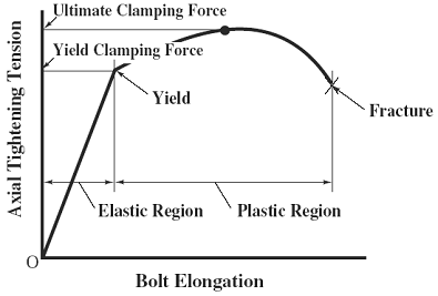
Relationship between Bolt Elongation and Axial Tightening Tension
Related:
- Torque Wrench Adapter for Reduced Arm Equation and Calculation
- Torque Clamp Force Calculator
- Stud Preload Calculator
- Bolt Preload Tension Equation and Calculator
- Bolt Preload Tension Force Calculator
- Torque vs Tension Bolts Table Chart SAE J429 Bolts
- Bolt Multiple Diameters Change of Length Under Axial Force Formula and Calculator