Related Resources: calculators
Diameter Change in Compression Spring Calculator
Extension Spring Hook Design Calculator and Equations
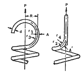
The hooks at the ends of extension springs are subjected to both tension (bending) and torsional stresses. These combined stresses are frequently the limiting factor which determines the characteristics of the spring. These stresses occur at the base of the hooks and their magnitude is higher than the stress in the body. This, then, is the weakest point in an extension spring nd the stresses should be calculated. the allowable working stresses should not exceed those shown in Equation 2.
Preview Extension Spring Hooks Design Calculator
The bending stress at Section A is calculated using:
Eq. 1
The torsional stress at section A is calculated using:
Eq. 2
Where
P = load
R = distance from load to central axis
d = diameter of wire or side of square
r1 = mean radius of hook
r2 = mean radius of bend
r3 = inside radius of hook
r4 = inside radius of bend

Figure 1, Typical Hook End
For best results, the inside radius should be at least twice the wire diameter. Special ends can be used when high stresses occur in the hooks. By using smaller diameter for the last few coil before the hook, the magnitude of PR is reduced. Thus, the stress is reduced in direct proportion to the decrease of PR is reduced. Thus, the stress is reduced in direct proportion to the decrease of PR. By using as large radii for r3 and r4 as the design will permit, the stress is further reduced.
- Bell Helicopter Structural Design Manual, 1977
Related
- Diameter Change in Compression Spring Calculator
- Coil Spring
- Compression Spring Calculator
- Compression Spring "k" Constant Calculator
- Compression Spring Assembly Operating Life and Reliability Equations and Calculator
- Mass Spring Simulator and Calculator
- Mechanical Engineers Pocket Book Premium Membership Required to view Document/Book
- Parallel Springs Stiffness Constant Equations and Calculator
- Series and Parallel Spring Rate Formula and Calculator
- Series and Parallel Mounted Springs Stiffness Constant Equations and Calculator
- Tapered Flat spring cantilevered design equations and calculator
- Torsion Spring Calculator
- Torsion Applied Spring Stiffness Constant Equations and Calculator
- Coil-Diameter Tolerances of Torsion Springs Specifications
- Shear Stress Helical Linear Spring Calculator
- Series Mounted Springs Stiffness Constant Equations and Calculator
- Spring Helix Wire Length Formula and Calculator
- Spring Properties and Material
- Spring Terminology
- Springs Made From Rectangular Section Bar Steel Design and Calculations
- Stresses in Helical Springs Produced by Shocks Formulas and Calculator
- Torsion Spring Design Formula and Calculator
- Torsion Spring Arc Length Formula and Calculator
- Wave Washer Design Formula and Calculator