Related Resources: gears
Parallel-Sided Splines Table Calculator
Gear Design Engineering Tools Data Knowledge Menu
SAE Parallel Side Splines Table of Sizes and Dimensions
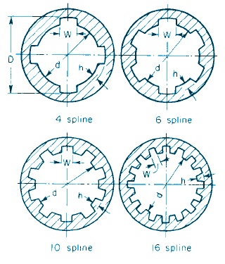
Parallel-side spline's have been standardized by the SAE for 4, 6, 10, and 16 spline fittings.
* Tolerance allowed of -0.001 in for shafts 3⁄4 to 13⁄4 in, inclusive; of -0.002 for shafts 2 to 3 in, inclusive; -0.003 in for shafts 31⁄2 to 6 in, inclusive, for 4-, 6-, and 10-spline fittings; tolerance of -0.003 in allowed for all sizes of 16-spline fittings.
^ Tolerance allowed of -0.002 in for shafts 3⁄4 in to 13⁄4 in, inclusive -0.003 in for shafts 2 to 6 in, inclusive, for 4-, 6-, and 10-spline fittings; tolerance of -0.003 allowed for all sizes of 16-spline fittings.
Figure 1, Parallel-sided splines.

Source:
Marks Standard Handbook for Mechanical Engineers
Related:
- Spline Transmitted Torque and Pressure Analysis Formula and Calculator
- Involute Spline Engineering Drawing Data
- Involute Spline ANSI B92.1 Equations and Design
- Involute Spline and Serration Universal Design Calculator
- Spline Socket Go and No Go Gages
- The Shaft Design Book
- Key and Spline Drive Bit Tools per. ASME B18.3
- Torque Applied Deformation and Stress of a Shaft with Four Keyways Equations and Calculator
- Torque Applied Deformation and Stress of a Shaft with One Spline Equations and Calculator
- Torque Applied Deformation and Stress of a Shaft with Two Splines Equations and Calculator
- Torque Applied Deformation and Stress of a Shaft with Four Splines Equations and Calculator