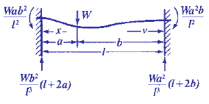
Beam Deflection and Stress Equations Calculator for Fixed at Both Ends, Load at any location Beam
Beam Deflection and Stress Formula and Calculators
Area Moment of Inertia Equations & Calculators
Structural Beam Deflection, Stress, Bending Equations and calculator for a Beam Fixed at Both Ends, Load at any location.

Beam Moment and Loads at Supports
M = Wab2 / l2
W1=(Wb2 / l3))(l + 2a)
Open: Moment and Loads at Supports Calculator
Beam Section Modulus Z
Z = I/z
I = Moment of inertia Cross Section : Units in4 (m4)
z = Distance neutral axis to extreme fiber: Units in (m)
General Beam Stress at any Given Point
Beam Stress For segment length a,
![]()
Beam Stress For segment length b

Open:Stress for Segment a and b Calculator
Beam Stress at Critical Locations Points
Beam Stress at end nearest to segment of length a,
![]()
Beam Stress at end nearest to segment of length b,
![]()
Open:Stress at end nearest a or b Calculator
Maximum Beam stress is at end nearest to shorter segment.
Beam Stress is zero at
![]()
and
![]()
Greatest negative Beam stress, at load
![]()
Open:Greatest negative stress at load Calculator
Beam Deflection at any Point
For length a,
![]()
For length b
![]()
Open: Deflection at any point Length a or b Calculator
Critical Beam Deflections
Beam Deflection at load
![]()
Open: Deflection at Load Calculator
If b length is the longer segment and a is the shorter one.
The maximum Beam deflection is in the longer segment:
![]()
and

Where:
| E = | Beam Modulus of Elasticity | psi | (N/mm2) |
| I = | Beam Moment of Inertia | in4 | (mm4) |
| W = | Beam Load | lbs | (N) |
| s = | Beam Stress at the cross-section being evaluated | Lbs/in2 | (N/mm2) |
| y = | Beam Deflection | inches | (mm) |
| x = | Some distance as indicated | inches | (mm) |
| u = | Some distance as indicated | inches | (mm) |
| a, b = | Some distance as indicated | inches | (mm) |
| L = | Some distance as indicated | inches | (mm) |
| l = | Some distance as indicated | inches | (mm) |
Z = |
section modulus of the cross-section of the beam = I/z | in3 | (mm3) |
z = |
distance from neutral axis to extreme fiber (edge) | inches | (mm) |
- Please note letter "l" (lower case "L") is different than "I" (Moment of Inertia).
- Deflections apply only to constant cross sections along entire length.
References:
- Any Machinery's Handbook published since 1931 or,
- Machinery's Handbook, 21st Edition
- Machinery's Handbook, 23st Edition
- Machinery's Handbook, 27st Edition
Related
- Maximum Shear Stress Theory Fatigue of a Shaft or Axle Formula and Calculator
- Shaft Torsional Deflection and Rigidity Formulas and Calculator
- Static Loading Shaft or Axle Analysis Formula and Calculator - Most shafts are subject to combined bending and torsion, either of which may be steady or variable. Maximum Shear Stress and Von Mises Stress
- Combined Loading on Offset Link, Circular Cross Section, in Direct Tension Equation and Calculator
- Combined Loading Offset Link, Circular Cross Section, in Direct Compression Equation and Calculator
- Combined Loading Offset Link, Rectangular Section, in Direct Tension Stress Equation and Calculator
- Combined Loading Offset Link, Rectangular Section, in Direct Compression Stress Equation and Calculator
- Beam Deflection Calculator Supported on Both Ends With Overhanging Supports of equal Length and Equal Loads
- Beam Deflection Equations Calculator Supported on Both Ends Loaded Two equal Loads
- Beam Deflection Equations Calculator with Ends Overhanging Supports and a Two Equal Loads applied at Symmetrical Locations
- Beam Deflection Equations Calculator with End Overhanging Supports and a Single Load
- Beam Deflection Equations Calculator Cantilevered Beam with One Load Applied at End